
How to Use the AUTOOL ATL-4.5D Two-Post Lift: A Safety-First Operator Guide

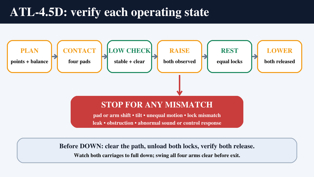
The normal AUTOOL ATL-4.5D operating cycle is: confirm the exact lift and vehicle plan, position the vehicle, place all four pads on vehicle-maker lifting points, engage all four arm rotation restraints, pause at low height for contact and stability checks, raise under continuous observation, then rest both carriages on equal mechanical safety locks before work begins. To lower, clear the complete travel path, unload and release both carriage locks, lower under control, reach full down, and swing every arm clear before the vehicle leaves.
This is a trained-operator guide for normal use of a professionally installed, commissioned, and load-tested standard-width ATL-4.5D. It does not teach installation, anchoring, electrical or hydraulic work, cable or lock adjustment, repair, or first load testing. If the nameplate, installed controls, vehicle lift-point data, commissioning record, or current instructions do not agree, stop and have the lift supplier or qualified service provider resolve the difference.
In this guide
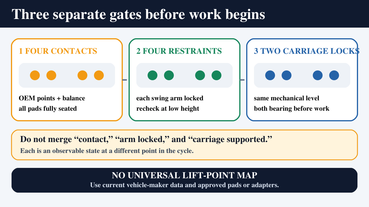
- The operating idea: four contacts, four arm restraints, two carriage locks
- Confirm the exact lift before using this guide
- Before the first operating cycle
- Pre-shift pass/fail gate
- AUTOOL ATL-4.5D operating steps
- Stop-work conditions
- Delivered-configuration record
- Is the ATL-4.5D the right two-post lift for your shop?
- Final operating checklist
The operating idea: four contacts, four arm restraints, two carriage locks
A two-post lift has several safety states that must not be merged into one vague “locked” check.
- Four contacts: every pad must fully contact a correct vehicle-maker lifting point. Contact alone is not enough if the point, adapter, reach, weight distribution, or center-of-gravity plan is wrong.
- Four arm restraints: each swing arm’s rotation restraint must be completely engaged before the vehicle is raised beyond the initial contact check. Recheck them at low height.
- Two carriage locks: after raising to working height, both left and right carriages must bear on equal mechanical safety positions before under-vehicle work begins.
Arm restraints prevent the arms from rotating away from the selected points. Carriage safety locks support the two moving carriages at a mechanical position. They do different jobs and are checked at different moments.
Confirm the exact lift before using this guide
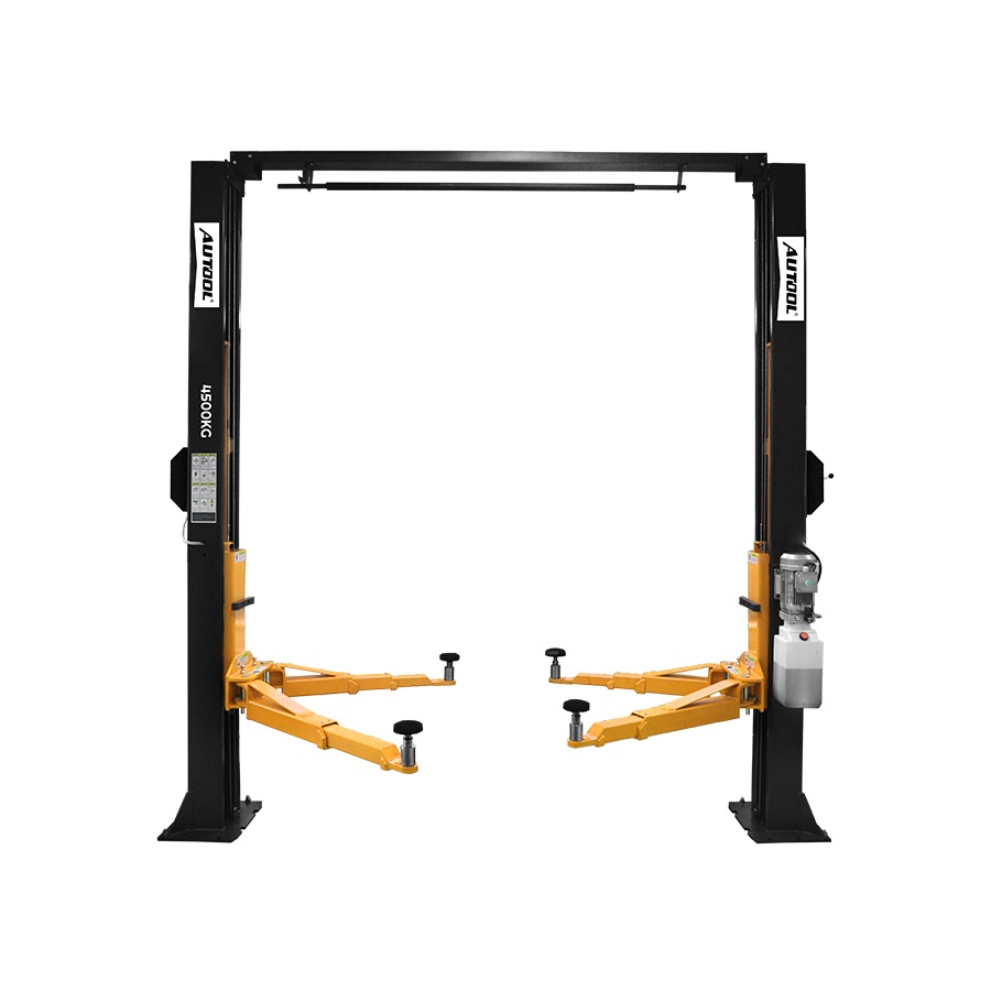
This page covers the standard-width AUTOOL ATL-4.5D, not the wider ATL-4.5DW and not another ATL model. The current manual describes a front three-section arm pair and a rear two-section arm pair. Confirm that arrangement against the delivered lift and its nameplate; never infer model identity from appearance alone.
Current official literature publishes a 4,500 kg rated capacity, 3,900 mm overall height, 2,860 mm inner post width, 95 mm minimum pad height, and 1,990 mm lift height. It also publishes 660–1,050 mm for the three-section arms and 910–1,350 mm for the two-section arms. These are fit-screen values, not permission to lift a particular vehicle.
Before accepting a job, verify all of the following together:
- the vehicle’s actual weight and front-to-rear distribution;
- the vehicle maker’s current lifting points and restrictions;
- the required point span and each arm’s usable reach;
- pad and approved adapter limits, including any system derating;
- the vehicle and task center of gravity;
- overhead, door, gantry, and underbody clearance;
- whether removing or installing a heavy component will shift balance.
The manual drawing and current store table do not publish the same overall-width value for the standard model. Use the serial/order-specific drawing and written supplier confirmation for site or purchasing decisions. Do not use this operating article to lay out a bay or approve an installation.
Before the first operating cycle
A lift handover should leave the workshop with an unambiguous model, control method, current manual, commissioning and load-test record, inspection schedule, emergency/isolation procedure, approved adapters, and a qualified service contact. The operator also needs hands-on training on the installed controls and observable lock behavior.
Do not improvise if the delivered controls differ from the manual. The audited manual describes a manual safety-release control used with an oil-return control during lowering. Current product information mentions more than one possible control configuration. The labels and handover for the installed, serial-specific lift determine what the operator uses.
Pre-shift pass/fail gate
Complete the workshop’s recorded pre-use inspection before admitting a vehicle. This is an observation gate, not a repair procedure.
- Clear the zone. Check the floor surface, post area, arm sweep, carriage travel, overhead path, and vehicle route. Remove tools, stands, hoses, cords, parts, and other obstructions.
- Inspect visible lift components. Look at the posts, carriages, arms, pads, adapter retainers, pins, arm restraints, mechanical safety locks, equalizing ropes, hydraulic hoses, wiring, labels, and fasteners accessible to the operator.
- Check the pads. Pad surfaces must be clean, intact, and able to seat fully. Oil, loose debris, severe wear, damage, or an unapproved adapter is a failed gate.
- Check for leaks and damage. Any hydraulic leak, damaged wiring or rope, bent or loose component, missing label, unusual wear, or prior unresolved defect stops use.
- Check unloaded behavior only as trained. Under the site’s approved procedure, confirm that motion, stop controls, arm restraints, and both carriage locks behave as demonstrated during handover. Do not adjust a component to make the check pass.
If any check fails, isolate the lift according to site procedure, mark it unavailable, and call qualified service. A fault is not cleared merely because the lift still moves.
AUTOOL ATL-4.5D operating steps
Step 1: Assign one operator and control the lift zone
One trained operator should control the cycle and maintain a clear view of the vehicle and both carriages. Keep customers, bystanders, and unassigned workers outside the arm-sweep, travel, and potential fall zones. No one remains inside the vehicle during lifting or lowering.
Completion check: one operator is responsible, communication is understood, and the complete zone is clear.
Common mistake: allowing a second person to position an arm or retrieve a tool while the operator is at the controls.
Stop if: anyone enters the controlled zone or the operator loses sight of a critical area.
Step 2: Identify the exact lift and installed controls
Read the lift nameplate and the installed control labels. Confirm that the unit is the standard-width ATL-4.5D, its rated capacity is legible, and its control and lock-release method matches the training and current delivered instructions. Check the shop’s defect log before use.
Do not apply ATL-4.5D dimensions or control steps to an ATL-4.5DW, a relabeled unit, or an unverified variant.
Completion check: model, capacity, power/control state, manual, and prior defect status all agree.
Common mistake: treating a combined D/DW sales page as a serial-specific operating document.
Stop if: the nameplate is missing or unclear, labels conflict with the manual, or a defect remains open.
Step 3: Make a vehicle-specific lifting and balance plan
Obtain the vehicle maker’s current lift-point information for the exact model, wheelbase, powertrain, and relevant option package. Confirm actual vehicle weight and distribution rather than relying only on a broad model estimate. Select only approved pads or adapters, verify their ratings and engagement, and make sure all four arms can reach without binding or overextension.
Plan the supported center of gravity inside the four-point support geometry. A vehicle below 4,500 kg can still be unsuitable if its distribution, point location, adapter limits, or task creates an unstable state. Never raise one side only.
If the job removes or installs a heavy battery, engine, transmission, axle, body, tank, or other major component, plan the resulting center-of-gravity change and approved auxiliary support before lifting. “We will add a stand later” is not a balance plan.
Completion check: documented points, weight/distribution, four-arm reach, adapter ratings, balance, overhead clearance, and the complete task all pass.
Common mistake: using a universal front-engine positioning ratio or copying pad locations from a different vehicle.
Stop if: any point, weight, adapter, reach, balance, or task-induced shift is uncertain.
Step 4: Put the lift fully down and swing all arms clear
Confirm both carriages are fully lowered and the arms and pads are outside the vehicle approach path. Position any approved adapters as instructed without creating a trip or tire-contact hazard. Keep the operator’s side and planned exit route open.
Completion check: the vehicle can enter without crossing an arm, pad, adapter, hose, tool, or person.
Common mistake: leaving a low-profile arm inside a tire path because it appears to fit under the vehicle.
Stop if: a carriage is not fully down or any support cannot be cleared from the route.
Step 5: Position and secure the vehicle
Guide the vehicle between the posts according to the vehicle-specific plan. Use a spotter only under the site’s communication procedure, with that person outside pinch and crush zones. Stop the engine, secure the transmission and parking brake as required by the vehicle maker and shop procedure, remove the key or otherwise prevent unintended movement, and have every occupant leave.
Vehicle position is correct only when the approved points are reachable, the arm geometry is sound, and the planned center of gravity remains supported. It is not determined by a memorized body seam, mirror, door, or wheel location.
Completion check: vehicle is secured, empty, centered for the approved four-point plan, and clear overhead.
Common mistake: moving the vehicle until the arms “just reach” and accepting poor arm angles.
Stop if: tire, body, running board, battery pack, exhaust, or undertray prevents correct point access.
Step 6: Position all four arms and pads
Swing the arms beneath the vehicle while it remains fully supported by its tires. The audited manual identifies the three-section pair at the front and the two-section pair at the rear; verify that this matches the delivered lift and intended vehicle orientation.
Place every pad or approved adapter directly under its vehicle-maker point. Center and seat each support exactly as the vehicle-maker and approved-adapter instructions require, and make sure extensions and retainers engage as designed. Do not contact plastic trim, an undertray, a battery enclosure, a suspension part, or an unapproved seam because it is nearby.
Completion check: four correct points, four fully seated support devices, sound arm geometry, and no interference.
Common mistake: setting three pads accurately and treating the fourth as a height adjustment rather than an independent lifting point.
Stop if: a pad cannot sit fully on the specified point or an adapter must be improvised, stacked, or used beyond its limit.
Step 7: Engage all four arm rotation restraints
Check each arm’s rotation restraint individually. All four must be completely engaged so an arm cannot swing away as the vehicle leaves the floor. Count the four observable states; do not assume a click on one side proves the other arms are secure.
These are the arm restraints, not the carriage safety locks used at working height.
Completion check: front-left, front-right, rear-left, and rear-right restraints are each fully engaged.
Common mistake: checking only the arms closest to the controls.
Stop if: any restraint will not engage completely, has excess movement, or changes arm position.
Step 8: Inch upward to establish four-pad contact
From a position with a clear view, raise only enough for the first pad to touch. Stop. Adjust the remaining approved pad heights until all four pad faces contact their exact points fully and evenly. Keep the tires on or only just clear of the floor during this contact-setting stage.
Watch the arms as load begins to transfer. No pad should slide, roll onto an edge, compress trim, or pull an arm away from its planned geometry.
Completion check: all four pads have full, correctly located contact and the four arm restraints remain engaged.
Common mistake: continuing to raise as soon as the first two pads touch.
Stop if: contact shifts, the vehicle attitude changes unexpectedly, or any point is hidden and cannot be verified safely.
Step 9: Pause at low height for the complete safety gate
Raise only until the tires are just clear, then stop. From outside the fall zone, perform the shop-approved low-height stability check. Inspect all four contacts, all four arm restraints, adapter engagement, vehicle attitude, arm clearance, underbody clearance, door/roof/gantry path, and both carriage positions.
The manual refers to a gentle stability check. Do not forcefully push, rock, bounce, or climb on the vehicle. The purpose is to detect an invalid support state at the lowest practical height—not to prove that a marginal setup can withstand abuse.
Completion check: four contacts and four arm restraints are unchanged; the vehicle is level as planned, stable under the approved check, and clear throughout the intended lift path.
Common mistake: treating “tires off the floor” as permission to raise directly to full height.
Stop if: any pad or arm moves, the vehicle tilts, slips, rocks, or the clearance or balance state is uncertain.
Step 10: Raise to the required height under continuous observation
Keep every person clear and operate the raise control continuously only while the path is safe. Watch the vehicle, both carriages, arms, pads, hoses, ropes visible to the operator, and overhead clearance. Raise only as high as the task requires.
Both sides should move smoothly and remain equal. Be alert for delay, jerk, vibration, friction, unusual sound, interference, or a changing vehicle attitude.
Completion check: the required height is reached with equal, smooth carriage movement and unchanged support geometry.
Common mistake: watching only the vehicle roof and missing unequal carriage motion.
Stop if: motion becomes unequal or abnormal, clearance reduces unexpectedly, or any person or object enters the path.
Step 11: Rest both carriages on equal mechanical safety locks
At the selected working height, use the trained control sequence to place both carriages on mechanical safety positions at the same level. Confirm that both sides are bearing as intended and the vehicle remains stable before anyone enters the under-vehicle work area.
Hydraulic pressure alone is not the normal supported work state. One carriage on a lock and the other at a different position is also not an acceptable state.
Completion check: two carriages, equal mechanical safety positions, stable vehicle, controls neutral.
Common mistake: hearing one lock and assuming both have seated equally.
Stop if: either lock cannot be confirmed, the two sides differ, or the vehicle attitude changes while seating.
Step 12: Work without invalidating the balance plan, then clear the bay
Perform only the task covered by the original lift and balance plan. Keep tools, stands, drain equipment, hoses, cords, and removed parts organized outside unintended contact paths. Never use the lift as a crane or raise one side independently.
Before removing or installing a heavy component, reassess the center of gravity and apply the approved auxiliary-support plan. A stable vehicle can become unstable after its mass changes.
When work is complete, account for people, tools, parts, stands, doors, hood, tailgate, cables, hoses, and floor equipment. Check the vehicle is reassembled and secured for lowering as required by the repair procedure.
Completion check: balance remains valid and the full vehicle, carriage, arm, and floor path is clear.
Common mistake: clearing the floor but leaving a tall stand or open panel in the lowering path.
Stop if: the task changed mass distribution without an approved support plan or any obstruction cannot be removed.
Step 13: Unload and release both locks, then lower under control
Keep the zone empty. Raise only enough, using the trained procedure, to unload both carriage safety locks. Verify that both can release together before lowering.
On the manual-control configuration described in the audited manual, the trained operator uses the installed safety-release and oil-return controls together while observing both sides. Releasing the safety control during descent should allow the locks to re-engage and stop travel. If your installed labels, controls, or handover differ, do not translate this description into a guessed button or handle sequence—use the delivered instructions or stop and contact qualified service.
Lower with a clear view of both carriages and the vehicle. Maintain continuous observation for equal movement, interference, changing support contact, or a person entering the zone.
Completion check: both locks released as trained and both carriages lower equally, smoothly, and controllably.
Common mistake: continuing to lower when one side hesitates or a lock appears to re-engage.
Stop if: both locks do not release together, one side binds, motion is unequal, a control behaves unexpectedly, or clearance is lost.
Step 14: Reach full down, clear the arms, and close the cycle
Lower until the vehicle is fully supported by its tires and both carriages reach the normal full-down state. Release the load completely from all four pads. Only then swing every arm and support clear of the vehicle path.
Confirm there are no tools, adapters, cords, leaks, or loose items beneath or beside the vehicle. Have the operator direct vehicle exit. Power down or isolate the lift according to shop procedure and record any abnormal condition observed during the cycle.
Completion check: full down, four supports clear, route clear, vehicle ready to exit, defects recorded.
Common mistake: driving away while a low pad or arm remains under a sill or tire path.
Stop if: any pad remains loaded, an arm cannot clear, the vehicle contacts the lift, or a new leak or defect appears.
Stop-work conditions
Stop motion, keep people out of the hazard zone, and isolate the lift under site procedure if you observe any of these conditions:
- a pad or arm moves, or the vehicle tilts, slips, rocks, or changes attitude;
- any arm restraint fails to engage or any carriage lock differs from the other side;
- the actual weight, distribution, lifting point, adapter rating, or center of gravity is uncertain;
- either carriage moves late, unevenly, jerkily, or with abnormal vibration;
- the vehicle approaches the gantry, ceiling, door, or another obstruction;
- a hydraulic leak, damaged wire or rope, loose or deformed component, or missing label is visible;
- an unusual sound, friction, interference, delay, or unexpected control response occurs;
- the repair task changes vehicle balance outside the approved support plan.
Do not diagnose, adjust, bypass, or “cycle through” the problem using this article. Mark the lift unavailable and involve a qualified service provider.
Delivered-configuration record
Keep the following information in the bay’s lift record and verify it after any supplier-authorized change:
| Item | What the record should establish |
|---|---|
| Exact identity | ATL-4.5D standard-width nameplate, serial/order, manufacture or document revision |
| Bay geometry | Accepted serial-specific drawing; published sources differ on overall width |
| Arm arrangement | Delivered front/rear arm types, usable ranges, pads, adapters, and ratings |
| Controls | Installed raise, lower/oil-return, safety-release, stop, and isolation labels |
| Lock behavior | Observable four-arm-restraint and two-carriage-lock states demonstrated at handover |
| Power and installation | Installed supply and site acceptance recorded by qualified parties |
| Documentation | Current delivered manual, commissioning/load-test record, inspection schedule |
| Support | Training record, emergency procedure, qualified installer/service contact |
Is the ATL-4.5D the right two-post lift for your shop?
The 4,500 kg rating and published geometry make the ATL-4.5D a candidate for a range of workshop vehicles, but the buying decision should begin with the actual vehicle mix and site—not capacity alone. Sample the longest, shortest, lowest, tallest, front-heavy, rear-heavy, and awkward-point vehicles you expect to service. Check their OEM points, weight distribution, arm reach, adapter needs, door access, roof clearance, and common component-removal tasks.
Also confirm unloading access, qualified installation and site engineering, local inspection requirements, operator training, spare parts, and service response before ordering. The current official store page combines D and DW choices, so request written confirmation of the ATL-4.5D standard-width configuration, supplied controls, electrical option, current drawing, adapters, lead time, and documentation. Select ATL-4.5D deliberately and obtain written, order-specific confirmation before purchase. If you purchase through that model link, OBD2SCAN may receive a commission.
Final operating checklist
Safe normal operation is a chain of observable states: four correct contacts, four engaged arm restraints, a passed low-height gate, equal raising, two carriages bearing on equal mechanical locks, a balance-preserving work phase, both locks unloaded and released for controlled descent, full down, and all arms clear.
If one state cannot be proved, do not move to the next. That discipline matters more than memorizing a generic control sequence—and it keeps an online guide in its proper role: preparation and reinforcement for trained use, never a replacement for the delivered manual, vehicle-maker lifting data, site procedure, or hands-on instruction.






Comments 0
Questions, fixes, and real-world diagnostic notes from readers.
Be the first to share a diagnostic result or ask a follow-up question.