
How to Use the AUTOOL ATL-4.5F Four-Post Lift: A Safety-First Operator Guide

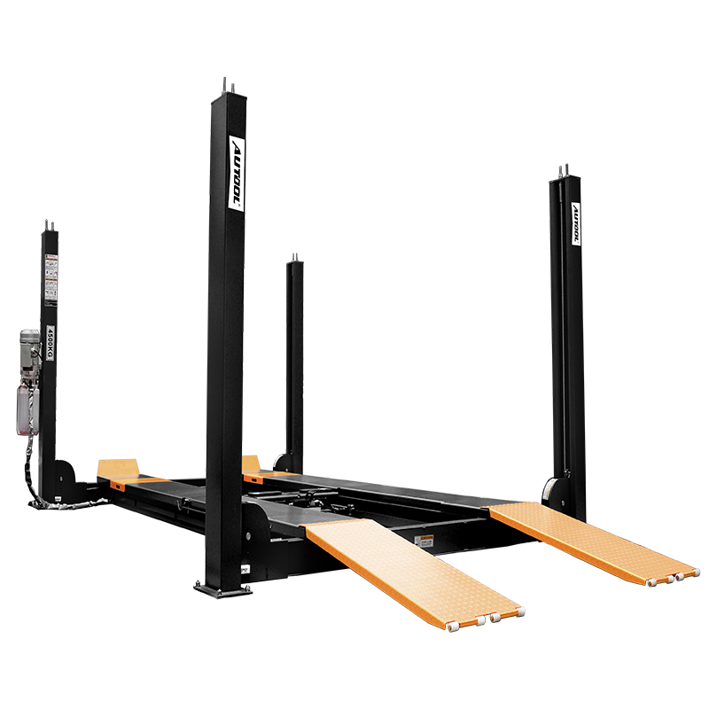
The AUTOOL ATL-4.5F is a drive-on, four-post lift with a published rated capacity of 4,500 kg. The operator’s key control is to treat the mechanical locks as a distinct working state—not as a sound heard while passing through.
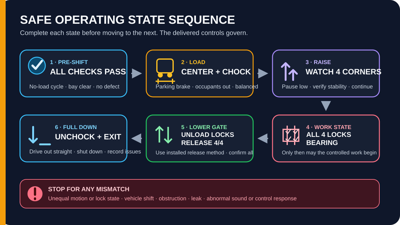
After a pre-shift, no-load check, center the vehicle on both runways, apply the parking brake, have every occupant exit, and chock the wheels at the front and rear. Raise under continuous observation, then lower gently until all four columns are carrying the platform on their mechanical locks. After the work is complete, clear the bay, raise only enough to unload the locks, release and confirm all four locks, lower fully, remove the chocks, and drive straight out.
Only trained and authorized personnel should perform this cycle. The August 2026 manual describes a manual lock-release arrangement, while current product information also lists an automatic version. Identify the controls fitted to your delivered lift during handover; never guess which release sequence applies.
Scope and disclosure: This guide was prepared from the exact-model manual, current official product information, and exact-product images. OBD2SCAN did not install, commission, load-test, or operate this lift. Installation, anchoring, electrical work, hydraulic adjustment, lock adjustment, wire-rope replacement, repair, secondary-lift operation, and wheel-alignment measurement are outside this guide.
Last reviewed: August 26, 2026.
What this guide covers—and what it does not
This is an operator guide for a professionally installed, commissioned, and handed-over ATL-4.5F. It explains the normal vehicle-loading, raising, locked-working, unlocking, lowering, and exit cycle. It also shows the visible conditions that mean “continue,” “complete,” or “stop.”
It is not an installation manual. Published sources disagree on material site and configuration details, including foundation requirements, motor power, maximum lift height, the included secondary lifting device, and the lock-release version. Those points must be resolved from the nameplate, delivered manual, order documents, current site drawing, and written supplier or installer confirmation—not by selecting the most convenient value from a web page.
The ATL-4.5F is marketed for wheel-alignment bays, but a four-post lift is not a wheel aligner by itself. Alignment work also depends on the installed turntable/slip-plate arrangement, the vehicle, the aligner, calibration, and the aligner manufacturer’s procedure. This page does not turn an equipment label into an alignment procedure.
In this guide
- Before the first operating cycle
- Know the two safety systems you must observe
- Pre-shift check: use a pass/fail gate
- Step-by-step: the normal ATL-4.5F operating cycle
- Stop-work conditions: do not turn these into DIY troubleshooting
- Verify your delivered ATL-4.5F configuration
- Is the ATL-4.5F the right four-post lift for the job?
- The state sequence is the real operating skill
Before the first operating cycle
Do not treat “the lift powers on” as a completed handover. Before the first vehicle enters, confirm all of the following:
- The product label and nameplate identify the delivered unit as ATL-4.5F.
- The nameplate rating, voltage, and control configuration match the order and handover documents.
- A qualified installer has completed installation, leveling, commissioning, safety checks, and the required load testing for that delivered configuration.
- The current, order-specific operating information is available at the lift.
- You can identify the installed raise, lower, lock-release, stop, and power-isolation controls from their labels and your training.
- You know whether lock release is manual, automatic, pneumatic, or another supplied configuration.
- The indoor site, foundation, electrical supply, and any required air supply have been accepted for this installation.
- Any center trolley, jack, beam, turntable, or slip plate has been identified as included or optional and has its own operating instructions.
If any answer is uncertain, pause before operating. Web specifications cannot safely complete an incomplete handover.
Capacity is only one part of the load decision
Treat 4,500 kg as the main lift’s upper rated limit, not as automatic approval for every lighter vehicle.
The delivered nameplate and load-distribution rules still govern. The vehicle must sit parallel to the two runways, with its load balanced across them. One-sided lifting or one-sided runway movement is prohibited. Confirm the vehicle’s actual weight and distribution rather than relying only on a model’s advertised curb-weight range.
Removing or installing a heavy engine, battery pack, axle, or other assembly can move the vehicle’s center of gravity after it is elevated. Stop and use an approved support plan if the work changes the balance assumption. The lift’s rating does not cancel that stability risk.
Know the two safety systems you must observe
Mechanical locks define the working state
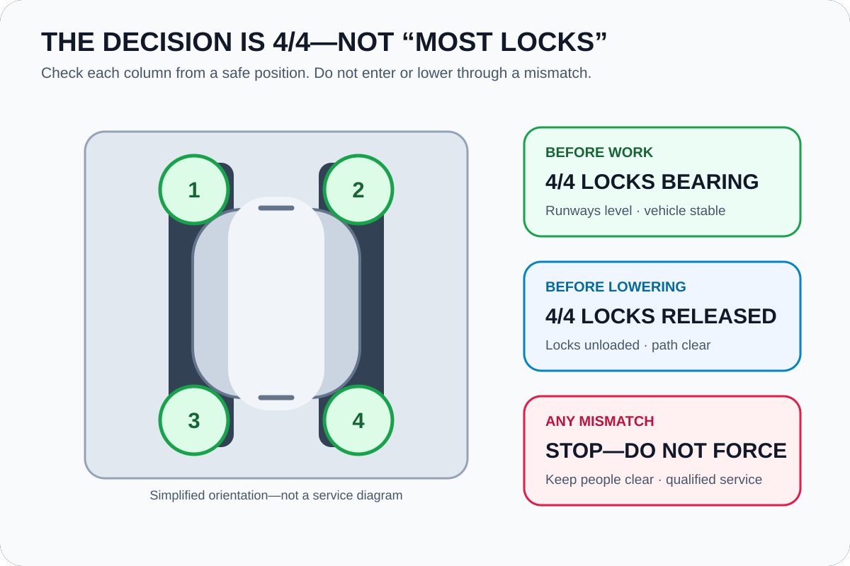
Spring-loaded hooks engage safety bars at the columns. During raising, the hooks pass successive lock positions. At the selected height, the operator lowers the platform gently until the hooks carry the load.
That is the working state: all four locks are bearing correctly, the runways are level and parallel, and the vehicle is stable. “The platform reached the right height” is not enough.
Before lowering, raise the platform only far enough to remove the load from the locks. Then use the release method fitted to your lift and confirm that all four hooks have released. Do not force a handle, bypass a hook, or continue lowering while one corner remains engaged. The mechanism diagram is useful for orientation; adjustment belongs to qualified service.
Wire ropes synchronize the platform; their visible condition matters
The wire ropes synchronize platform movement, so a problem in one rope path can affect a corner. Operators should inspect visible rope and attachment areas daily. Responsible personnel should also complete the broader weekly inspection specified for the delivered lift, including rope paths, fixed points, connectors, pulleys, broken wires, and corrosion.
Stop using the lift if you see broken wires, corrosion, deformation, a loose connection, abnormal wear, a damaged pulley area, or corners that no longer move or lock together. Do not use an online threshold as permission to continue. Record the observation, isolate the lift under the site procedure, and have qualified service inspect it.
Pre-shift check: use a pass/fail gate
Perform the check before a vehicle enters the bay. The result is binary: all checks pass, or the lift remains out of service.
1. Check the bay
The runways, approach path, space under the lift, and overhead travel path must be clear. Remove tools, hoses, stands, debris, oil, and grease that could create an obstruction or slip hazard. Keep customers and bystanders outside the lift area.
2. Check visible structure and safety parts
Look at the posts, crossbeams, runways, ramps, wheel stops, chocks, lock areas, and visible fasteners. Nothing should appear cracked, bent, loose, missing, modified, or out of position. Safety labels and control labels must be present and legible.
3. Check ropes and the hydraulic area
Inspect accessible, visible rope sections and connections for damage, corrosion, deformation, looseness, or abnormal wear. Look for a hydraulic leak or damaged hose from a safe position. Check the pump-station oil level only by the supplied procedure; never open or loosen a pressurized hydraulic component.
4. Perform the no-load function check
Use the controls identified during handover. The platform should rise while the raise control is commanded and stop when it is released. At a suitable low test position, confirm that lock action occurs at all four columns. Unload and release the locks by the supplied method, then verify controlled lowering and stop response.
Listen and watch throughout the check. The four corners should move together without unusual noise, jerking, delay, contact, leakage, or different lock behavior.
Pass condition: The bay is clear, visible parts are intact, no leak or rope abnormality is present, controls respond as trained, and all four corners raise, lock, release, and lower together. Any failed condition takes the lift out of service.
Step-by-step: the normal ATL-4.5F operating cycle
Step 1: Prepare the bay and assign one operator
One trained operator should control the lift and the vehicle-loading decision. Wear the work clothing, safety footwear, and other protective equipment required by the supplied instructions and workshop risk assessment. Clear the entire travel zone and confirm that no customer, bystander, tool, stand, hose, or loose object can enter it.
Completion check: The operator has an unobstructed view of the vehicle, both runways, and the people around the lift.
Common mistake: Multiple people give commands or approach different corners. Use one operator and a clear site communication rule.
Stop: Do not begin if the view is blocked or the area cannot be controlled.
Step 2: Approach straight and center the vehicle
Set the runways and approach area exactly as established during installation and handover. Drive onto the runways slowly and straight. Keep the vehicle parallel to the tracks, with every tire fully supported and the load centered across the lift.
If a spotter is needed, the spotter must remain in a designated visible safe position—not between a moving vehicle and a post, ramp, or wall.
Completion check: All tires are securely on the intended runway surfaces, the vehicle is parallel, and no bodywork, underbody part, tire, or accessory is contacting a post, ramp edge, stop, or center assembly.
Common mistake: Correcting a poor approach by raising one side or accepting a tire near a runway edge. Lower or drive out, then reposition the vehicle; never compensate with one-sided lift movement.
Stop: Do not lift a vehicle whose weight, distribution, dimensions, ground clearance, or runway fit is uncertain.
Step 3: Secure the vehicle and clear all occupants
Apply the parking brake. Switch the vehicle off under the workshop procedure, have the driver and every passenger exit, and place approved wheel chocks at the front and rear of the wheels as specified in the delivered instructions.
Walk around from outside the danger area. Confirm the vehicle is stable and nothing hangs below or beyond the runways where it can catch during travel.
Completion check: No person remains in or on the vehicle; the parking brake is applied; chocks are seated; the lift area is clear.
Common mistake: Treating the parking brake as a substitute for chocks. Use both the parking brake and the specified front/rear anti-slip restraints.
Stop: If the vehicle cannot be restrained without interfering with lift movement, do not raise it.
Step 4: Raise under continuous observation
Take the operator position and use the installed raise control. Watch the vehicle and all four corners from the start of movement. Keep hands, feet, clothing, tools, and people away from moving parts.
Pause at a low height. Recheck that the vehicle remains parallel, centered, stable, and clear of obstructions. Continue only if the platform is moving evenly and the check remains satisfactory.
Completion check: The runways remain level and parallel, the vehicle has not shifted, and every corner responds together without contact, leakage, or abnormal noise.
Common mistake: Looking only at the control panel. The decision comes from the entire lift and vehicle state, not from a button or indicator alone.
Stop: Release the control immediately for tilt, unequal motion, slipping, rocking, interference, an unexpected sound, a leak, a burning smell, or an abnormal control response.
Step 5: Rest the platform on all four locks
At the selected working height, stop raising. Lower gently as trained until the mechanical locks bear in their openings. Inspect the condition at each column from a safe position.
Do not enter the workspace merely because you heard several clicks. Verify all four corners.
Completion check: All four locks are bearing, the runways are level and parallel, the vehicle is stable, and no corner is hanging differently from the others.
Common mistake: Leaving the platform supported hydraulically just above a lock position. The manual requires the platform to be locked before work below the elevated vehicle.
Stop: If one lock does not bear with the others, keep people out. Follow the trained safe-lowering/isolation procedure and call qualified service; do not adjust the lock or rope.
Step 6: Work without changing the balance assumption
Maintain control of the lift area. Do not allow occupants into the vehicle, rock the vehicle, disable a safety system, or create a one-sided load.
Before removing or installing a heavy component, reassess the center of gravity and the effect of any support device on capacity and stability. Use only the support method approved for the vehicle and lift configuration.
Completion check: The vehicle remains stable and the work does not alter the load distribution beyond the approved plan.
Common mistake: Assuming that a locked lift makes any component-removal sequence safe. Locks support the lift; they do not prevent the vehicle from becoming unstable on it.
Stop: Stop work if the vehicle shifts, a support moves, a lock/corner changes state, or the planned task changes the balance without an approved support method.
Step 7: Clear the entire travel path before lowering
Finish the work, then account for people, tools, parts, hoses, cords, stands, jacks, and other equipment. Confirm the vehicle is complete and stable enough to lower. Clear the space under, beside, above, and at both ends of the lift.
Return to the operator position with a full view of the moving area. Never use a wooden block, stand, or other object to force or guide the lift while lowering.
Completion check: The vehicle is secure, every person is outside the danger area, and nothing intersects the lift’s downward path.
Common mistake: Checking only beneath the vehicle. A ramp, tool cart, overhead object, or person near a post can also obstruct travel.
Stop: Do not move the lift until the obstruction or person is fully clear.
Step 8: Unload and release every mechanical lock
Raise only enough to remove the platform load from the locks. Use the lock-release method fitted to your delivered ATL-4.5F. Confirm that all four locks have released before commanding continuous lowering.
Do not copy a manual-release sequence onto an automatic-release unit, or assume an automatic function on a manual unit.
Completion check: All four lock positions are released and the four corners remain synchronized.
Common mistake: Pulling or holding a release control while the locks are still carrying the load. First unload the locks; then release them by the trained sequence.
Stop: If one lock remains engaged or a corner reacts differently, stop. Do not force, bypass, strike, or adjust the mechanism.
Step 9: Lower fully under continuous control
Use the installed lowering control and watch all four corners throughout travel. Keep feet, hands, clothing, tools, and bystanders away from the lift. The platform should descend smoothly and stop as expected when the control is released.
Completion check: The platform is at its minimum position, movement has stopped, the vehicle is stable on the runways, and the approach path is clear.
Common mistake: Turning away once the vehicle is near the floor. Continue watching until the platform is fully down and stopped.
Stop: Stop for unequal descent, a lock re-engaging unexpectedly, an obstruction, abnormal noise, jerking, leakage, or a control that does not respond as trained.
Step 10: Remove chocks, drive out, and shut down
Only after the lift is fully down should you remove the wheel chocks. Confirm the ramps and exit path are clear, then drive straight out slowly.
Return the lift to its minimum-height storage state and switch off or isolate power under the workshop procedure. Record any abnormality noticed during the cycle, even if the lift completed the movement.
Completion check: The vehicle is clear, the lift is fully down and shut down as required, the bay is orderly, and any defect has been reported.
Common mistake: Removing chocks early or driving out before the platform is fully settled. Full-down confirmation comes first.
Stop-work conditions: do not turn these into DIY troubleshooting
Stop the motion, keep people clear, and use the trained emergency or isolation procedure for the installed unit if any of these conditions occurs:
- A safety device, guard, label, control, rope, lock, runway, post, ramp, or connection is damaged, missing, loose, modified, or bypassed.
- The vehicle tilts, slips, rocks, contacts the lift, or no longer sits parallel and balanced.
- One corner rises, lowers, locks, or releases differently from the others.
- You hear an abnormal sound or see jerking, delay, leakage, smoke, or an abnormal control response.
- A wire rope shows broken wires, corrosion, deformation, looseness, or abnormal wear.
- Vehicle weight or load distribution is unknown, or a repair changes the center of gravity without an approved support plan.
- A person or obstruction enters the danger area.
Do not go beneath a load that is not confirmed on all four mechanical locks. Do not open the control box, loosen a hydraulic connection, adjust a lock or rope, or improvise an emergency descent from this article. Tag the lift out under the site procedure and contact qualified service.
Verify your delivered ATL-4.5F configuration
Use this table before first operation, after a document change, or before ordering. The point is not to choose between competing web values; it is to locate the controlling record for your unit.
| Item | Why it matters | What to verify |
|---|---|---|
| Main lift height | Published manual and page values differ. | Nameplate, delivered manual, limit setting, and current layout drawing. |
| Motor and supply | Published motor values differ, and single-/three-phase versions require different provisions. | Delivered motor plate, control cabinet, qualified electrical design, and local requirements. |
| Foundation and anchoring | Published foundation guidance conflicts materially. | Current order-specific foundation drawing, site assessment, installer acceptance, and local code. |
| Lock release | Manual and automatic versions are listed. | The installed mechanism, labeled controls, required air if any, and trained release sequence. |
| Secondary lift/trolley | One source calls auxiliary equipment optional; current pages list a 2-ton device. | What is physically included, its rating, supports/adapters, and its own instructions. |
| Hydraulic oil | The manual contains multiple grade statements. | Current service bulletin or delivered maintenance instructions for the site temperature and unit. |
| Air supply | Current automatic configurations list an air requirement, while the operating pages do not fully diagram it. | Whether your unit uses air, the accepted supply, isolation, and service procedure. |
| Product/lifting data | Self weight and shipping/package weight are different measures. | Engineering and handling data from the current installation pack; do not use a web shipping figure for floor design. |
| Conformity documents | A declaration page contains a model-string inconsistency. | Order-specific declaration, serial/model match, destination-market requirements, and installer record. |
| Marketing test claims | A product graphic is not your commissioning record. | Delivered load-test and commissioning documentation for the actual installation. |
Is the ATL-4.5F the right four-post lift for the job?
The operating cycle makes the purchase conditions clearer. Consider this type of lift only when the workshop can confirm site fit, vehicle fit, task fit, professional installation, trained operation, inspection responsibility, parts/service support, and the required accessories.
A drive-on four-post layout can suit vehicle positioning, inspection, service, storage, and an alignment-oriented bay. Wheel-off work typically requires an appropriate secondary lifting solution, and wheel alignment requires separate alignment equipment and procedures. Confirm those needs rather than assuming the main lift includes every function shown in a marketing image.
Before ordering, complete this fit check:
- Record the heaviest and longest vehicles, wheelbase range, ground clearance, tire width, and expected load distribution.
- Confirm runway fit, approach, ceiling, door, traffic flow, escape space, and the current approved site/foundation plan.
- List the work actually performed: drive-on inspection, storage, exhaust/suspension service, wheel-off work, or alignment.
- Obtain a written configuration list for locks, controls, voltage, air, trolley/jack, turntables, slip plates, ramps, and adapters.
- Confirm installation, commissioning, operator training, inspection intervals, service coverage, parts availability, and the controlling manual for the delivered serial/model.
Commercial disclosure: OBD2SCAN may earn a commission if you purchase through the following AUTOOL Store link. That relationship does not change the conflicts and limitations shown above.
If the fit check passes, you can review the current AUTOOL ATL-4.5F product configuration at AUTOOL Store. Confirm the delivered configuration in writing before treating any product-page image or value as final.
The state sequence is the real operating skill
Three checks control the entire cycle: the lift passes its pre-shift/no-load gate; all four mechanical locks carry the platform before work begins; and all four locks are unloaded and confirmed released before lowering continues.
At the end, the platform is fully down, the chocks are removed only in that state, the vehicle is out, power is handled under the site procedure, and abnormalities are recorded. If the delivered control version, site documentation, auxiliary-lift instructions, capacity/distribution, or lock behavior is uncertain, the correct next step is to pause and obtain qualified written confirmation—not to experiment.








Comments 0
Questions, fixes, and real-world diagnostic notes from readers.
Be the first to share a diagnostic result or ask a follow-up question.