
Coolant Leak Near the Water Pump? Diagnose Before Replacement

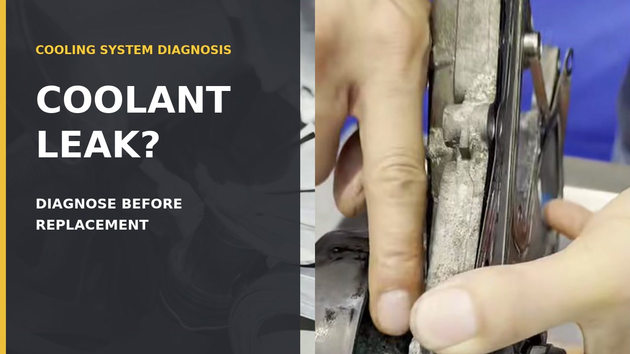
Coolant near a water pump is a clue, not a diagnosis. Coolant can run down from a connection or housing above it, while a belt or fan can spread it away from the source. Confirm the leak path before ordering a pump.
Stop before opening a hot system
If the temperature warning is active, steam is present, or coolant is disappearing quickly, shut the vehicle down safely and arrange recovery. Never open a hot or pressurized cooling system.
The short workflow
- Let the engine and cooling system cool fully.
- Record the fresh leak trail before cleaning anything.
- Inspect from the highest fresh wet point toward the apparent source.
- Use a compatible sealing test to determine whether the connected system holds under that condition.
- Locate the leak visually; do not let a pass/fail light name the component.
- Repair with exact vehicle information and the correct parts and coolant.
- Vacuum-fill if the vehicle and tool procedure permit it, then complete the specified bleed and verification routine.
In this guide
1. Make the vehicle safe and preserve the evidence
Park on a stable surface, switch the engine off and wait until the cooling system is fully cool. Keep people and animals away from spilled coolant, wear suitable eye protection and collect leakage rather than washing it into a drain.
Before wiping the area, photograph fresh wetness and dried residue. Note the coolant level only when the vehicle procedure permits it, the warning shown, when the loss appears and whether the engine had been running. Old residue can remain after a previous repair, so look for a fresh, advancing edge rather than relying on color alone.
Stop if access would put hands, clothing or test hoses near belts, fans, hot surfaces or high-voltage components. Use professional repair support when the access or procedure is outside your equipment and experience.
2. Trace the leak; do not diagnose from the lowest drip
With the system cool and the engine off, inspect accessible points above and around the wet area. Depending on the vehicle, possible paths may include:
- a hose, quick connector or clamp;
- a thermostat or coolant outlet housing;
- an expansion-tank or return connection;
- a radiator seam or nearby pipe;
- a water-pump housing, seal area or drain/weep path;
- residue thrown by a pulley, belt or fan.
Start at the highest fresh wet point and work downward. Clean only a small confirmed area at a time so the original trail is not erased. If everything is already wet, clean and dry the accessible area, then repeat a safe, controlled observation rather than guessing.
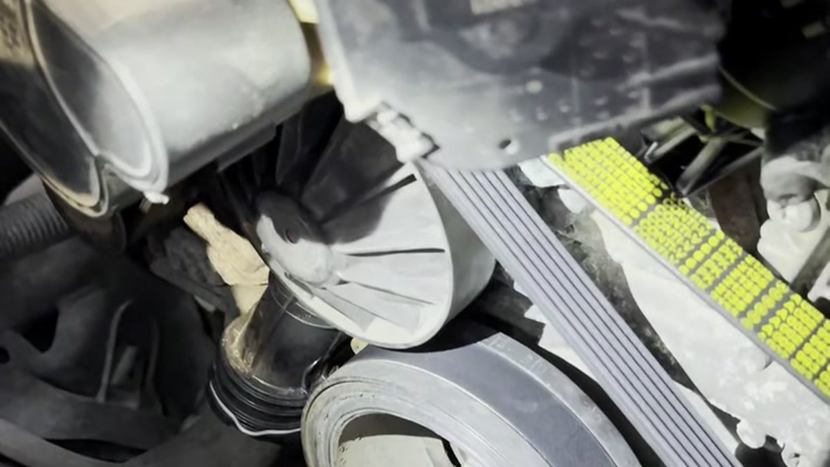
In the documented repair sequence, the visible trail sits among multiple housings and belt-drive components. The useful observation is the route of the residue—not an automatic conclusion that the nearest pulley or pump has failed.
Wet near the pump is not yet a pump diagnosis
Finding coolant around the pump supports further inspection. It does not prove whether the pump, its seal, its gasket, a connection above it or another component is responsible.
3. Use a vacuum-hold test for sealing evidence
A vacuum tester/filler can add one bounded observation: can the connected, closed system reach and hold the selected vacuum during the tool’s test sequence?
Use this type of equipment only when the system is fully cool, the vehicle procedure permits the test, the correct pressure-rated fill opening is identified, the adapter fits without force, the equipment passes its pre-use checks, and the setting follows both the vehicle information and tool instructions.
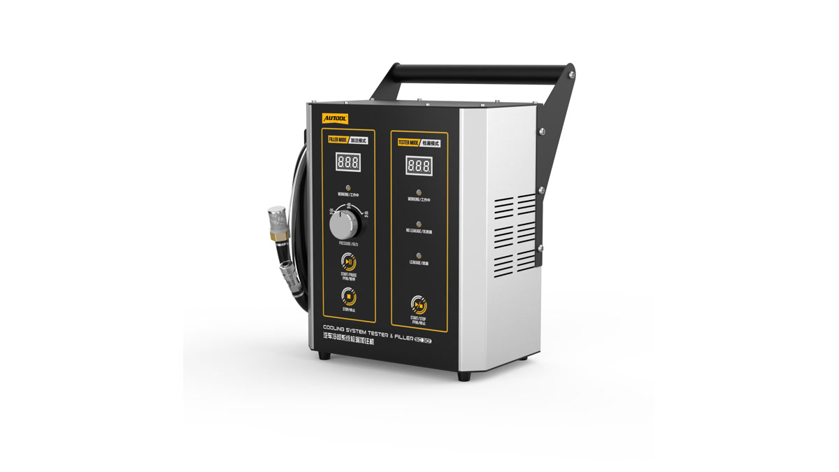
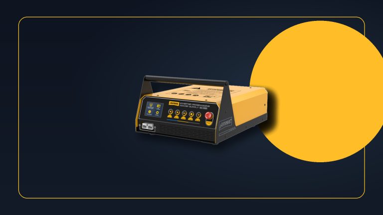
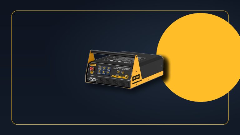
One compatible option for this bounded test is the AUTOOL SC301 cooling-system tester and vacuum filler when the vehicle has a compatible pressure-rated opening and the user has the required 12 V supply, suitable compressed air and exact procedure. Its manual specifies three selectable vacuum levels and a 60-second holding phase in Testing Mode; follow the current manual rather than copying a setting from another vehicle, and do not expect the tool to identify the leaking component or perform the repair.
Interpret the result without overreaching
| Observation | What it supports | What to do next |
|---|---|---|
| The target vacuum cannot be reached | The system, adapter, connection or tester may not be sealed under this setup | Stop and inspect the adapter/tool first, then look for fresh leakage |
| The tool indicates leakage after the hold | A sealing loss was detected during that test condition | Locate the source visually; the indicator cannot name the failed part |
| The tool indicates no leakage | No loss was detected by that setup during its limited test interval | Continue vehicle-specific checks if the complaint is intermittent, hot or rotation-dependent |
| Fresh coolant appears at a specific point | The location is stronger physical evidence | Confirm it is the highest origin and not runoff from above |
A green indication is not a lifetime “leak-free” certificate. A cold, static vacuum test may not reproduce a leak that appears only with heat, positive pressure, shaft rotation, vibration or load.
Vacuum and positive-pressure tests are different procedures
If your procedure instead calls for a manual positive-pressure tester, use the separate Cooling System Pressure Test: Safe Setup and Result Guide. Do not transfer a pressure-test limit or sequence to a vacuum tester.
4. Decide whether the water-pump diagnosis is supported
A pump diagnosis becomes more credible when fresh coolant can be traced to a pump-specific leak path and nearby higher sources, the adapter and test equipment have been excluded. Even then, use the exact vehicle’s service information to identify the component and access method.
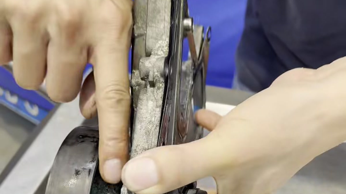
The removed component in this case shows concentrated residue at the pump edge. That is more specific than a puddle under the engine because it connects the visible trace to the component, but the image alone still cannot establish the failure mode, part fitment or correct repair procedure.
Do not condemn the pump when the only evidence is a puddle below it, the area was already covered in coolant, a connection above it is wet, the tester connection leaks, the symptom occurs only hot but only a cold check was performed, or the engine configuration has not been identified.
If the evidence remains mixed, label the result inconclusive. That is safer and usually cheaper than replacing an expensive component on location alone.
5. Keep mechanical repair vehicle-specific
Water-pump access and drive arrangements vary widely. On some engines the repair is part of an accessory-drive job; on others it can involve tightly packaged components or timing-drive work. Obtain current instructions for the exact VIN, engine and installed equipment before removing anything.
The parts and exposed mounting surface below show why these must be separate decisions. A replacement assembly may use a separate gasket, while the exposed engine face has multiple sealing paths and fastener locations. Neither image provides a universal orientation, sealant rule or torque sequence.
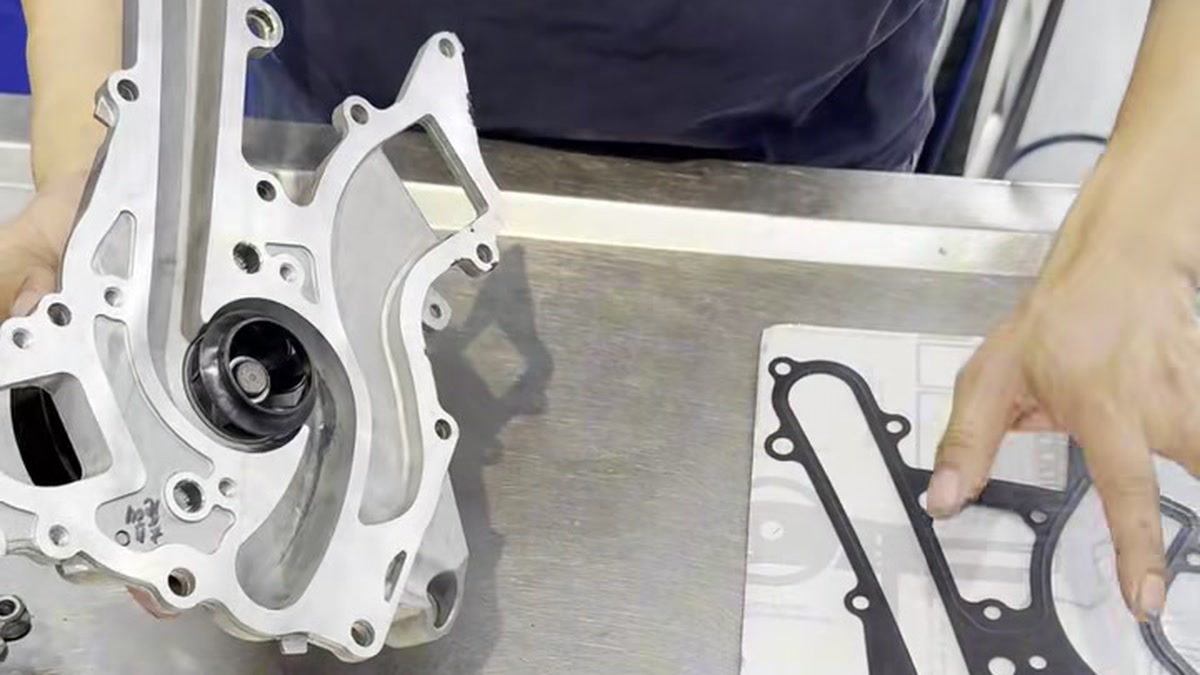
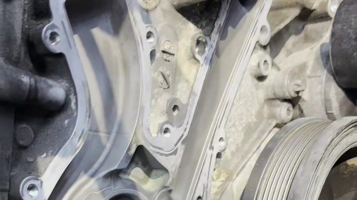
The repair plan must establish the correct pump and seals, coolant specification, drain and capture method, surface preparation, fastener sequence and torque, belt/timing requirements, refill method and bleed procedure. This guide intentionally supplies none of those model-specific values.
If you cannot verify that information or safely perform the work, use professional repair support. A vacuum tester does not mechanically repair the leak.
6. Vacuum-fill only after the fault is repaired
Once the confirmed fault has been corrected, a compatible vacuum filler can help evacuate the system and draw in specified coolant. The SC301 manual says Filling Mode creates vacuum and then automatically begins filling; more than one cycle may be needed if the system does not fill completely.
Before filling, verify that the adapter and vehicle support the procedure, prepare the exact coolant and concentration specified for the vehicle, keep the supply hose positioned as the tool instructions require, and follow the current valve sequence. Vacuum filling does not replace the vehicle’s bleed procedure.
If the tool cannot achieve the selected vacuum, reports a fault, draws no coolant or the system loses vacuum, stop. Recheck the connection and repair before continuing.
7. Verify the repair in more than one condition
After filling, complete the vehicle-specific bleed and operating check. Monitor coolant level and temperature as the manufacturer directs, confirm cabin-heat behavior where relevant, and inspect the repaired area without reaching into moving components.
After the vehicle has cooled again, recheck the specified level and inspect for fresh residue. If the procedure permits, repeat the bounded sealing test and record the setup, selected setting, hold result and visible evidence. A successful conclusion should combine the test result with a dry repair area and normal vehicle behavior—not a single indicator light.
Final checklist
- The cooling system was fully cool before opening or connecting.
- The highest fresh wet point—not merely the lowest drip—was recorded.
- Adapter and tester sealing were checked before blaming the vehicle.
- The test result was treated as condition-limited evidence.
- The failed component was located physically before parts were ordered.
- Exact vehicle information controlled the repair, coolant and bleed steps.
- Refill and post-repair verification were documented separately.



Comments 0
Questions, fixes, and real-world diagnostic notes from readers.
Be the first to share a diagnostic result or ask a follow-up question.