
AUTOOL EM Readouts: What They Can Tell a Fisker Ocean Workshop

An AUTOOL EM display can provide useful evidence during a defined low-voltage task, but the number on the screen is not a diagnosis. Read the displayed value alongside the equipment mode, the Fisker Ocean’s state at that moment, and what changed during a known interval. Without that context, even a steady value can be misleading.
On this page
Record four fields together:
- Reading: the value or equipment message actually displayed.
- Context: mode, vehicle state, elapsed time, and concurrent load or action.
- Useful for: documenting how the supply behaved during the specified task.
- Does not prove: battery health, the identity of a current consumer, module condition, or repair success.
Keep the EM supervised throughout the observation so an operator can respond immediately to an alert, thermal reduction, unstable connection, or unexpected change.
Voltage is a state-tagged observation
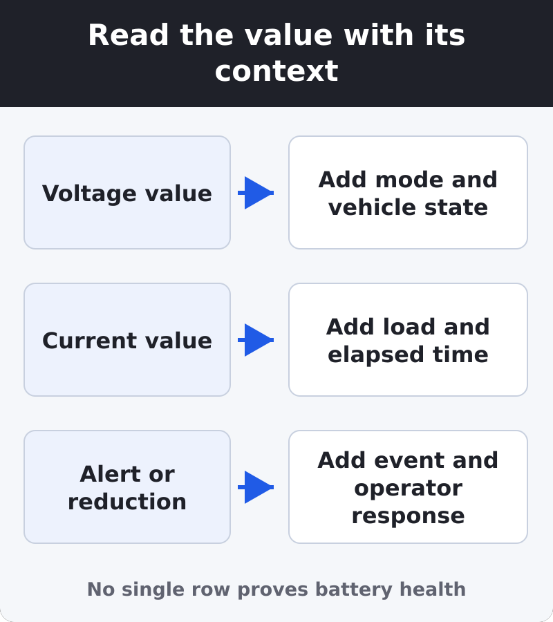
Record the displayed voltage with units, selected mode, start time, and vehicle state. Note whether the Ocean was parked, awake, or in a technician-defined service state, and whether an allowed load changed. A number recorded without those details cannot be compared responsibly with a later observation.
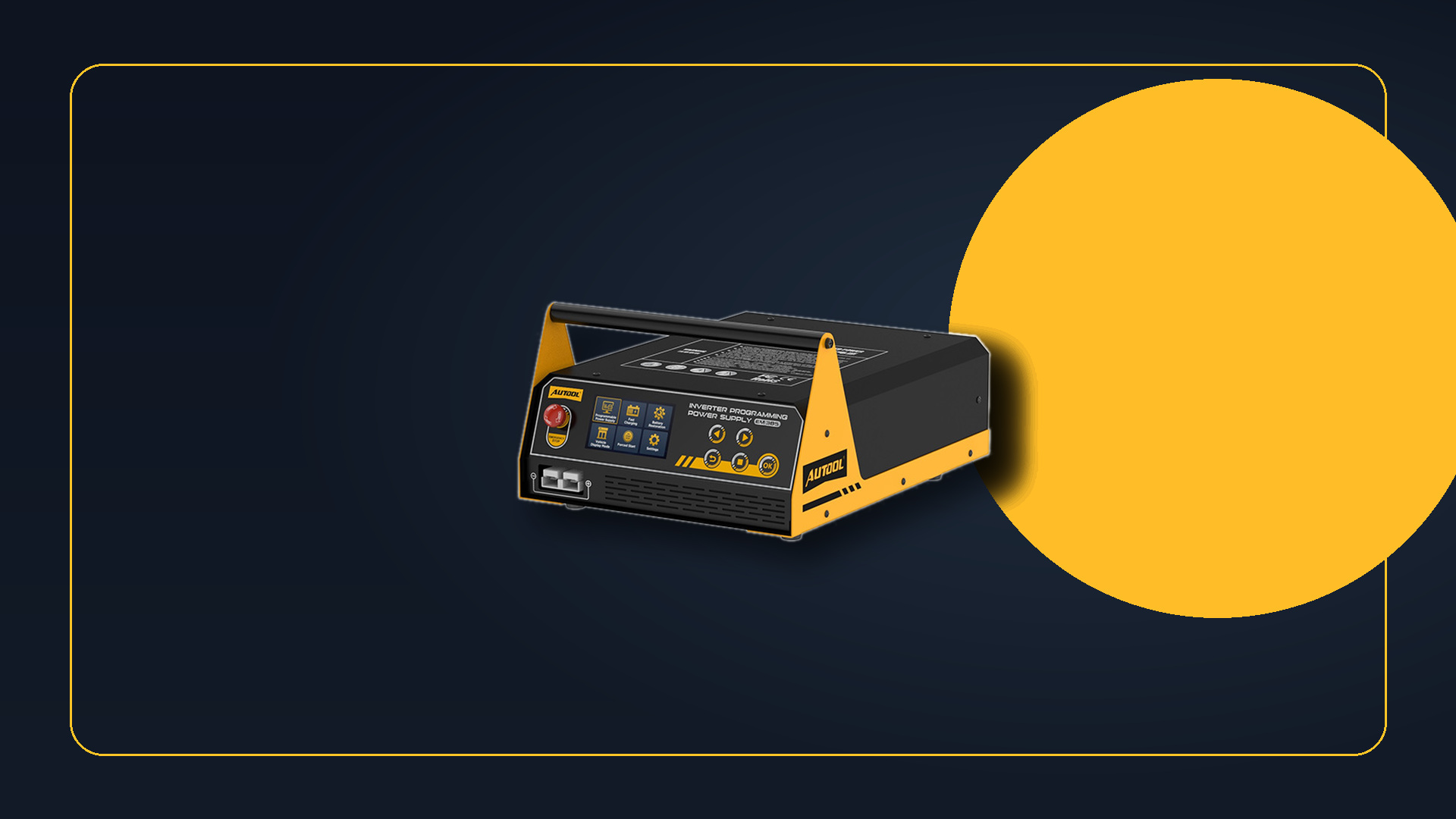
The AUTOOL EM355 provides charging and programming-support displays documented in the current manual, pages 19–20, in a physical-control format. That makes it useful for supervised low-voltage work when the current vehicle procedure supplies the setting. Its voltage display does not measure battery capacity or certify that the Ocean is free of electrical faults.
Voltage is useful for confirming that the equipment is operating in the intended documented range and for spotting a change that deserves investigation. It cannot, by itself, establish state of health, identify a weak battery, confirm a module fault, or prove that a software or service procedure completed correctly.
Do not create a generic Ocean pass/fail range from the equipment’s adjustable range. The acceptable value must come from the exact job instructions, battery requirements, and measurement point.
Current needs load context and elapsed time
A current observation becomes useful when it is tied to what the vehicle and equipment were doing. Record the value, elapsed time, selected mode, and any approved action that occurred at the same moment. If a fan, display, actuator, or other load changes, note the event rather than treating the new current as a free-standing diagnosis.
The AUTOOL EM365 includes a named vehicle-display mode and operating readouts documented in the current manual, pages 19–21. Its current readout can document the supply’s contribution during a defined state, but total supplied current does not reveal which module consumed it and does not prove a parasitic draw.
One isolated reading also cannot answer whether the supply will remain adequate for the entire task. Duration matters. A technician assessing a long session needs a trace or a set of timed observations under controlled states, along with the procedure’s expected demand and interruption rules.
Status messages, alerts, and thermal reduction belong to the record
Equipment messages are evidence about the equipment and its immediate operating conditions. Record the exact message, mode, time, displayed values, environmental conditions, and what the operator did next. If available output is reduced as the supply heats, document the reduction as part of the session rather than silently using the earlier maximum.
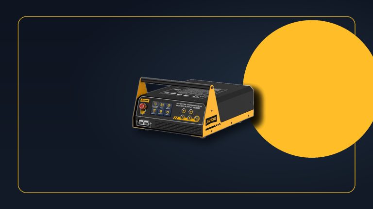
The AUTOOL EM385 combines touch controls with programming support, charging, display, and separate adjustable-equipment functions documented in the current manual, pages 18–22. Those controls can make mode and status information easier to organize, but an equipment alert is not an Ocean fault code and its separate DC-supply function is not vehicle diagnosis.
Treat reverse-polarity, connection, temperature, input, output, leakage, or short-circuit warnings as stop-and-check conditions under the exact manual. Do not repeatedly reset protection or use a disappearing warning as proof that the original cause is resolved.
What the battery and vehicle assessment must answer
A battery assessment must answer questions the supply display cannot: capacity, state of health, ability to hold charge, and suitability for continued service. A vehicle electrical diagnosis must identify unexpected consumers under controlled conditions, distinguish normal state changes from abnormal draw, and evaluate relevant modules and software with appropriate diagnostic equipment.
Repair verification is another separate task. It compares the vehicle with the applicable completion criteria, including any required scan, calibration, functional check, or road test. A stable support display can be part of the record, but it is not the completion criterion.
Use the current Fisker 12 V information for vehicle-side battery cautions, then let the exact service procedure define the state and acceptable readings. If either is unavailable, the responsible conclusion is “not enough context,” not a green or red verdict.
If one of the EM models fits a documented supervised task, enter coupon code HCM6E4GZ at checkout and confirm acceptance and the final total before paying.




Comments 0
Questions, fixes, and real-world diagnostic notes from readers.
Be the first to share a diagnostic result or ask a follow-up question.