
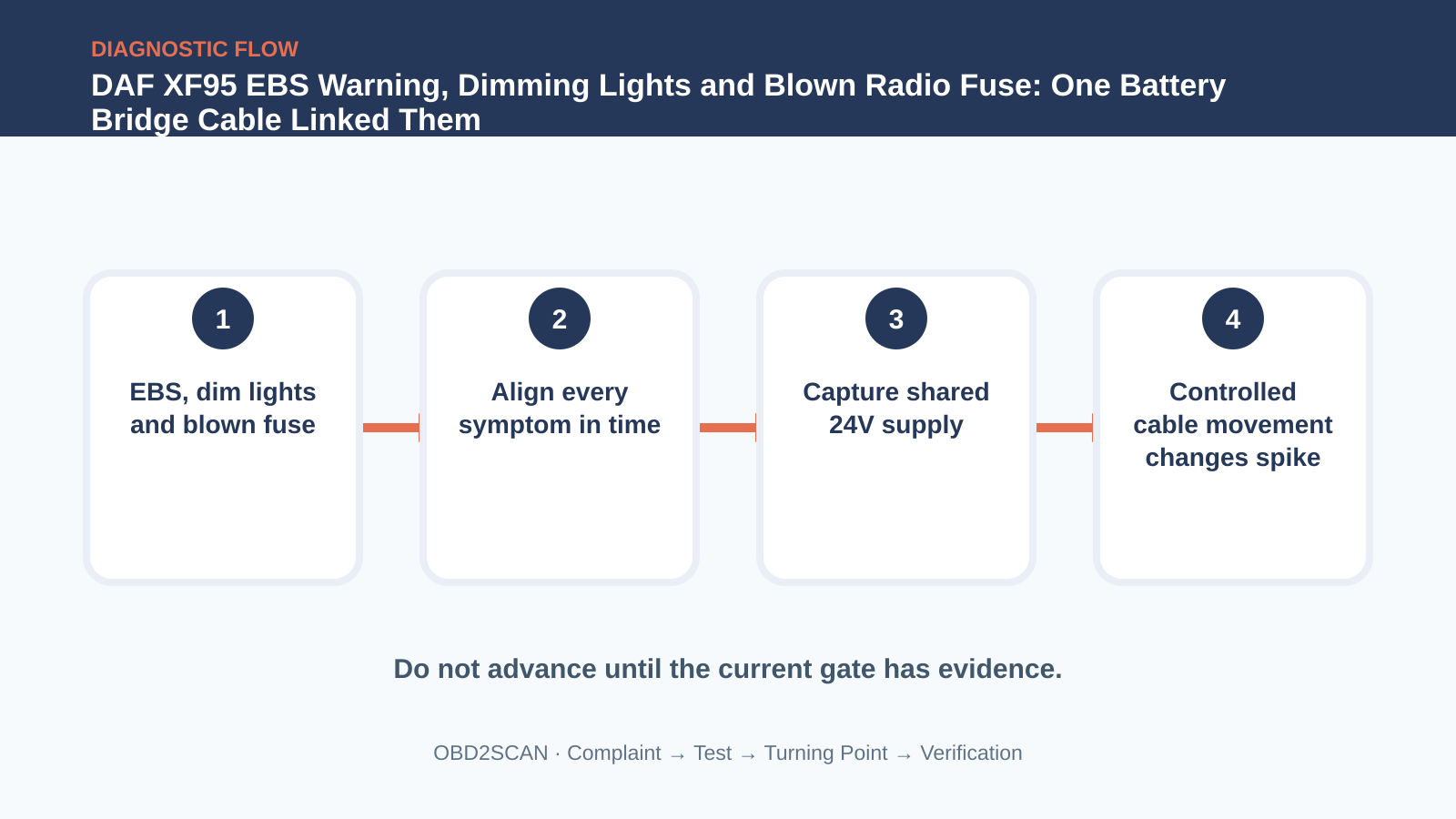
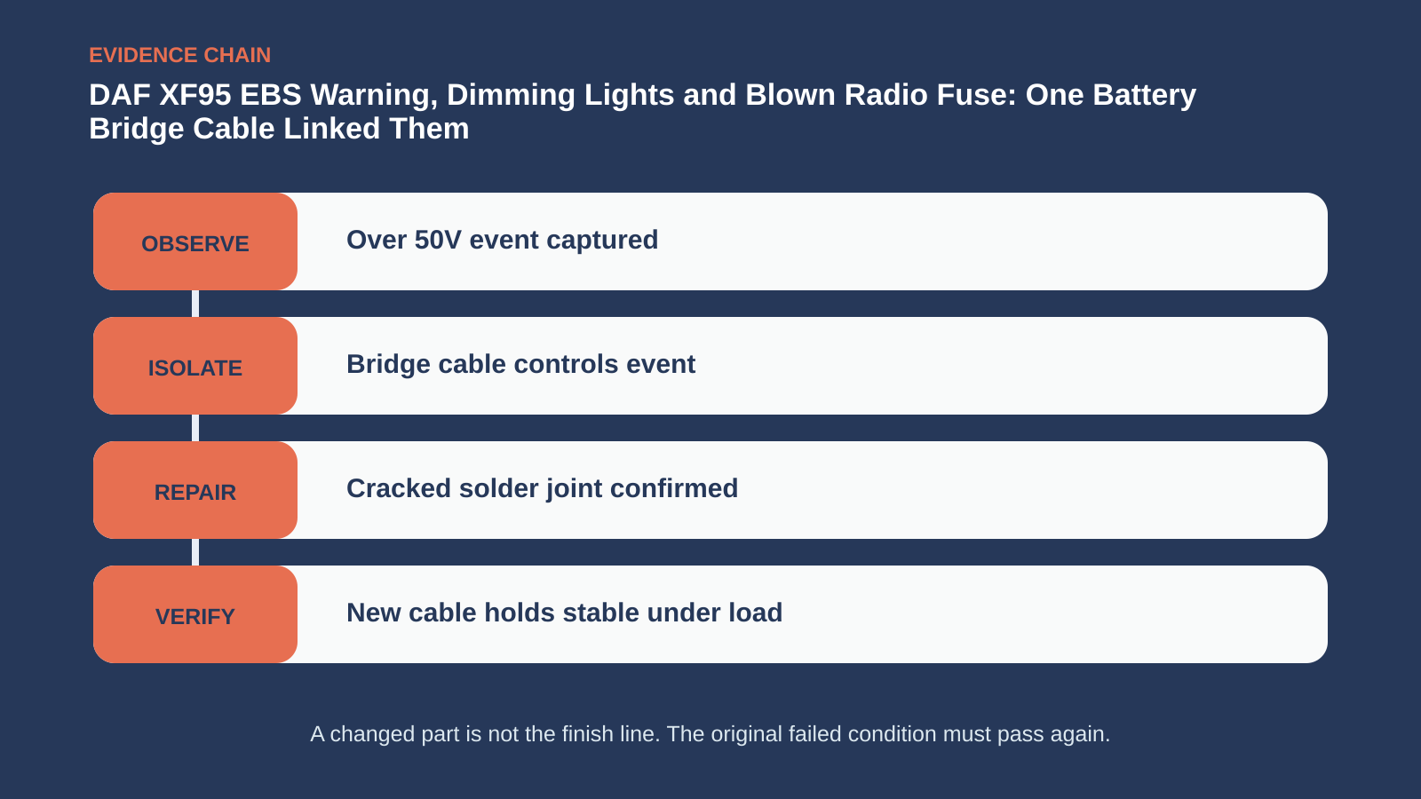
DAF XF95 EBS Warning, Dimming Lights and Blown Radio Fuse: One Battery Bridge Cable Linked Them

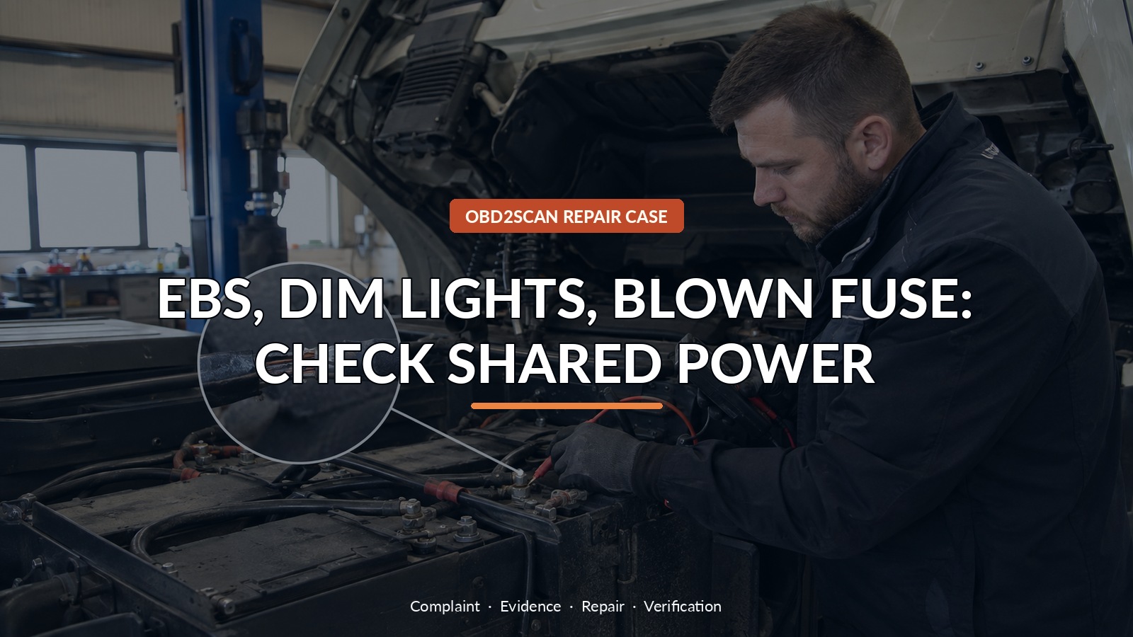
Ebs, Dim Lights, Blown Fuse: Check Shared Power
A DAF XF95 presented what looked like three jobs: an intermittent EBS warning, cabin lights that dimmed, and a radio fuse that blew. Scan history complicated the picture with EBS undervoltage and engine-ECU overvoltage records. Put on one timeline, those contradictions stopped being noise and began pointing toward the truck’s shared 24-volt foundation.
A circuit analyzer rated for the system voltage can support identified feed, ground and loaded voltage-drop checks. The MRCARTOOL B550 is specified for 9–30V systems and fits that narrow layer after DAF information identifies the points. B550 is specified for 9–30V systems and can support identified DAF feed, ground, continuity and loaded voltage checks; it cannot safely capture every high-energy transient, replace a current clamp or justify probing an unknown circuit that has already exceeded its normal voltage range.
The fault capture exceeded 50 volts. Controlled movement of the battery bridge cable stopped the disturbance, and inspection confirmed a cracked solder joint. Replacing the cable stabilized voltage across brake, engine and cabin loads. The powerful clue was synchronization: unrelated systems complained at the same instant because they shared one unstable source.
Quick answer: EBS warnings, dim lights and a blown radio fuse shared one unstable 24V source. A cracked battery bridge-cable joint produced extreme spikes.
In this guide
- Put every warning and cabin symptom on one timeline
- Check the 24-volt foundation under load
- Capture the event instead of clearing it
- Treat a 50-volt spike as a stop condition
- Use controlled cable movement to localize
- Open and inspect the bridge-cable joint
- Replace the complete compromised cable
- Verify stable supply across repeated loads
Put every warning and cabin symptom on one timeline
Build an event sheet before touching the batteries. Record whether the EBS lamp, lighting change and radio failure happen during crank, bumps, high electrical load or randomly. Save codes from every communicating module with status and time where available. Check battery security, electrolyte or case condition and cable heat. More than 50 volts on a nominal 24-volt vehicle threatens control units and lamps; if overvoltage is reproduced, stop normal operation and isolate the truck under the manufacturer’s procedure. Replacing a radio fuse while the supply is unstable is not safe diagnosis.
Check the 24-volt foundation under load
Test the pair of batteries individually and as a system. Measure resting voltage, cranking drop and charging response at battery posts, not only cable lugs. Add electrical loads while monitoring the main supply and key grounds. A healthy average reading can hide fast spikes, so min/max or a properly configured capture may be necessary. Treat batteries, series bridge, isolator, alternator and major distribution points as one power network. A defect between batteries can make modules see different realities at the same time.
Capture the event instead of clearing it
Intermittent power faults are often erased by switching the key off or disconnecting a battery. Capture first. Use appropriate attenuation and equipment rated for the expected transient; a circuit already showing extreme voltage is not the place for improvised leads. Trigger on an abnormal rise or fall and record EBS supply, engine ECU supply and cab response together where safe. The goal is to show whether one electrical event precedes several symptoms, not to create a dramatic waveform at the expense of test equipment.
Treat a 50-volt spike as a stop condition
A spike above 50 volts turns the job into damage prevention. Remove sensitive aftermarket devices if the approved procedure calls for it, and do not keep driving to make the warning return. Overvoltage can explain a blown fuse while a momentary open or imbalance can explain undervoltage elsewhere. Those code labels are not mutually exclusive when a series battery connection is unstable. Inspect for overheated terminals, swollen batteries and modules that no longer communicate before assuming the power repair will reverse every consequence.
| Symptom or record | Shared interpretation | Separate risk |
|---|---|---|
| EBS undervoltage | Supply collapses at brake module | Braking support may be limited |
| Engine ECU overvoltage | Same event overshoots elsewhere | Control-unit damage |
| Dimming lights | Human-visible supply instability | Bulb/driver stress |
| Radio fuse opens | Transient or excess current reaches cab branch | Radio may already be damaged |
Use controlled cable movement to localize
With the truck secured and the capture running, manipulate only accessible cable sections using an insulated, controlled method. Do not pull live high-current terminals by hand. In this case moving the battery bridge cable changed the fault immediately. That repeatable A/B response localized the problem far more strongly than visual inspection alone. Measure voltage drop across the connection under load, then isolate power before opening it. A cable can pass continuity with no load and fail dramatically when vibration or current shifts its cracked joint.
Open and inspect the bridge-cable joint
Inspection revealed a cracked solder joint in the bridge cable. Replace the complete compromised cable with the correct gauge, terminal geometry and environmental protection; a high-current series link is not a casual splice. Clean and torque posts to specification, support the cable so its mass does not flex the joint, and inspect companion connections for heat damage. Test both batteries again because repeated imbalance or overvoltage may have harmed one. Preserve photographs of the fracture so future intermittent-power cases have a local reference.
Replace the complete compromised cable
Verification must combine loads: crank the engine, operate lighting and cab systems, and monitor charging at idle and raised speed according to DAF procedure. Confirm voltage stays within the specified range with no captured spikes, dimming or hot connection. Rescan EBS, engine and body modules after a complete drive, and check that the radio branch holds its correct fuse. If a code returns, compare its timestamp with the new voltage log rather than assuming old history survived clearing.
Verify stable supply across repeated loads
Close the work order with one cause and several outcomes. The bridge cable explains the synchronized supply events; it does not automatically certify every exposed module. Note any residual communication, radio or battery concern separately and arrange follow-up. For the driver, the practical message is simple: multiple warnings plus changing lights justify stopping the truck, not cycling the key until they disappear. The human-visible symptom may be the earliest protection for expensive electronic systems.
Three apparent jobs became one power case when their timing was aligned. The cracked bridge cable was confirmed not by appearance alone, but by an event capture, a controlled movement test and a stable loaded system after replacement.









Comments 0
Questions, fixes, and real-world diagnostic notes from readers.
Be the first to share a diagnostic result or ask a follow-up question.