
How to Measure Superheat and Subcooling with MRCARTOOL L205

The MRCARTOOL L205 digital HVAC manifold gives you two pressures and two pressure-derived saturation temperatures, but it does not measure pipe temperature. To calculate superheat and subcooling, pair the L205’s low-side EV and high-side CO values with independent calibrated contact probes on the correct suction and liquid lines. The formulas are simple; identifying the refrigerant, line and stabilized test condition is the real work.
Quick answer: Select the exact refrigerant, zero the unpressurized L205, connect blue to low and red to high with both manifold valves closed, then stabilize the A/C under the vehicle’s specified test condition. Measure actual suction-line temperature and liquid-line temperature with calibrated contact probes. Superheat equals suction-line temperature minus L205 EV. Subcooling equals L205 CO minus liquid-line temperature. Compare only with the exact vehicle specification; do not charge by a generic target or by pressure alone.
In this guide
Know which temperatures are measured and derived
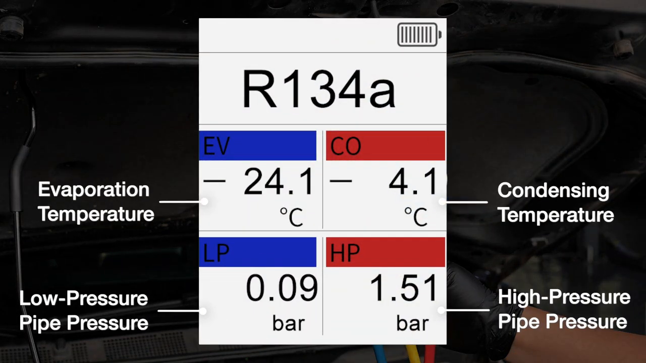
LP and HP are pressure measurements. EV is the saturation temperature calculated from low-side pressure for the selected refrigerant; CO is the saturation temperature calculated from high-side pressure. Neither is the temperature of the metal line. The L205 has no documented pipe-clamp temperature inputs, so its screen alone cannot display completed superheat or subcooling.
Actual suction-line temperature must be measured on the low-side vapor line at the specified location. Actual liquid-line temperature must be measured after the condenser on the liquid line, not on the hot compressor-discharge line. Use calibrated contact probes on clean metal, shielded from engine-bay radiant heat, and record all four temperatures at the same stabilized moment.
| Value | Source | Use in calculation |
|---|---|---|
| EV | L205 low-side pressure plus selected refrigerant | Subtract from measured suction-line temperature |
| Suction-line temperature | Independent contact probe on specified low-side vapor line | First value in superheat formula |
| CO | L205 high-side pressure plus selected refrigerant | First value in subcooling formula |
| Liquid-line temperature | Independent contact probe after condenser at specified point | Subtract from CO |
| Target range | Exact vehicle/OEM test procedure | Decides whether the calculated value is acceptable |
For recovery, evacuation, relative-vacuum mode, timed pressure hold, charging and controlled disconnection, use the complete MRCARTOOL L205 manifold guide. This procedure covers only operating measurements and calculations.
Before you start
- Work only if qualified for the refrigerant and vehicle; use suitable eye, hand and ventilation protection.
- Identify the refrigerant from reliable vehicle records or a refrigerant identifier, never from pressure resemblance.
- Obtain the exact charge mass, operating test condition, superheat/subcooling method and target from vehicle service information.
- Use clean, compatible, pressure-rated hoses and couplers; inspect the L205 connections and both valves.
- Prepare two calibrated contact temperature probes or a verified dual-channel thermometer.
- Identify low- and high-side service ports, the suction-line measurement point and the liquid-line measurement point.
- Confirm condenser airflow, cabin airflow, ambient conditions and compressor-control prerequisites can be reproduced safely.
Never vent refrigerant, crack a fitting to purge a hose or open both manifold valves during an operating pressure check. Recover and contain refrigerant with approved equipment.
Measure superheat and subcooling with MRCARTOOL L205
Step 1: Identify refrigerant and the required test state
Read the vehicle label and service information. Confirm refrigerant, exact charge specification, metering-device/control strategy and whether the procedure calls for superheat, subcooling or both. Different systems and operating modes do not share one target.
Write the required ambient range, engine speed, blower, recirculation, door/window state, condenser airflow and stabilization period. On hybrid or electric vehicles, follow high-voltage and electric-compressor precautions before touching service equipment.
Step 2: Prepare the L205 and temperature probes
With hoses disconnected and both pressure channels fully unpressurized, power on the L205 and long-press the mode/zero control to zero both sensors. Select the same pressure and temperature units you will use in the job record.
Place both contact probes together on one stable metal surface and compare them. If they disagree beyond the thermometer’s permitted tolerance, correct or replace the probes before calculating a small temperature difference.
Step 3: Connect low and high sides with valves closed
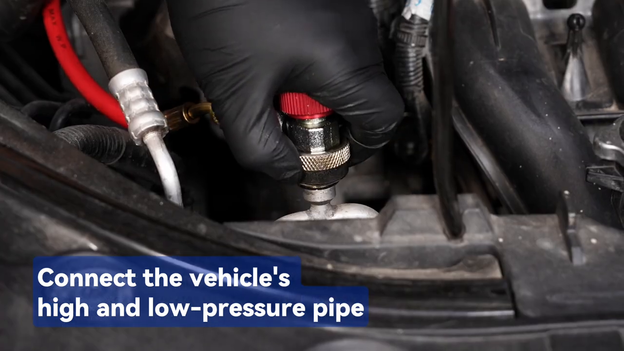
Keep the blue and red L205 manifold valves closed. Connect blue to the identified low-side port and red to the identified high-side port with compatible service couplers. The couplers expose each sensor to its own system side; the closed manifold valves prevent unintended flow through the center path.
Suspend the L205 where it cannot contact a belt, fan, exhaust surface or high-voltage part. Route hoses and probe leads away from moving components and verify that the hood cannot pinch them.
Step 4: Select the exact refrigerant
Enter refrigerant filling/pressure inspection mode and choose the exact refrigerant designation. EV and CO will be wrong if the database entry is wrong even when LP and HP pressure readings are correct.
The manual lists 92 refrigerants but excludes R717 and other ammonia refrigerants and limits R744 testing. Database presence is not proof that your hoses, couplers or service equipment are compatible. For a blend with temperature glide, confirm that the L205 saturation convention matches the vehicle procedure’s dew/bubble requirement.
Step 5: Place the suction-line probe
Find the low-side vapor or suction line at the location required by the vehicle procedure, often near the low-side service measurement point but away from compressor heat. Clean a small metal area and clamp the probe firmly with full contact.
Insulate the probe from under-hood air and radiant heat without covering a hot or moving component. Do not place it on the accumulator shell, rubber hose, compressor body or another convenient surface unless the procedure specifically defines that location.
Step 6: Place the liquid-line probe
Identify the high-pressure liquid line downstream of the condenser and upstream of the expansion device at the specified measurement point. Do not confuse it with the compressor-discharge line entering the condenser; that line carries hot vapor and produces an invalid subcooling calculation.
Clean the metal, clamp the second probe with comparable contact pressure and insulate it from ambient/radiant heat. Label the two channels so suction and liquid temperatures cannot be transposed in the worksheet.
Step 7: Stabilize the A/C under the specified condition
Start and operate the vehicle only after every hose and lead is secure and everyone is clear of moving parts. Apply the exact blower, mode, engine-speed and condenser-airflow condition. Keep both L205 manifold valves closed; this is observation, not charging.
Wait for the procedure’s stabilization criteria. On cycling or variable-displacement systems, record a defined stable interval rather than combining a pressure peak from one moment with a line temperature from another.
Step 8: Record LP, EV and suction-line temperature together
Read low-side pressure and EV from the L205 while reading the suction probe at the same moment. Record refrigerant, units, time and operating condition. EV is already the saturation temperature corresponding to that pressure and refrigerant selection.
Calculate superheat: suction-line temperature minus EV. Example only: if the line is 12°C and EV is 5°C, superheat is 7 K (a 7°C temperature difference). The example is arithmetic, not a target for the vehicle.
Step 9: Record HP, CO and liquid-line temperature together
At the same stabilized point, record high-side pressure and CO from the L205 plus actual liquid-line temperature from the second probe. Confirm the refrigerant and units have not changed on the display.
Calculate subcooling: CO minus liquid-line temperature. Example only: if CO is 45°C and the liquid line is 38°C, subcooling is 7 K. Do not compare a Celsius difference with a Fahrenheit target or mix readings from different compressor cycles.
Step 10: Check the calculation before interpreting it
If a result is negative or implausible, first recheck line identity, probe contact, insulation, selected refrigerant, units, zero condition and stabilization. A probe on the discharge line can make subcooling appear impossible; a probe too close to compressor heat can distort superheat.
Repeat one complete synchronized reading set. Do not average mismatched moments or adjust charge until the calculation is reproducible and the exact target/test method is confirmed.
Step 11: Interpret with system context, not a generic chart
Compare the result with the vehicle’s specified range and operating state. Airflow faults, compressor command, expansion-device behavior, sensor errors, restrictions and charge level can produce overlapping superheat/subcooling patterns.
Use pressures, line temperatures, vent temperature, ambient condition, compressor command and airflow evidence together. Charge by the documented mass and method after proper recovery and evacuation; do not add refrigerant merely to chase a familiar pressure or temperature difference.
Step 12: Close the observation and disconnect safely
Return the vehicle to the shutdown state required by the service procedure. Keep both manifold valves closed, isolate the service couplers and contain or recover trapped hose refrigerant using approved equipment. Never loosen a fitting to release pressure.
Remove both line probes, inspect the service ports and reinstall their caps. Save the synchronized readings, formulas, test conditions and resulting next diagnostic step in the job record.
Calculation and validation table
Every accepted result needs a pressure-derived saturation value, an independently measured line temperature and a vehicle-defined target.
| Calculation | Equation | Validation |
|---|---|---|
| Superheat | Suction-line temperature − EV | Correct suction point, same moment, exact refrigerant |
| Subcooling | CO − liquid-line temperature | Liquid line after condenser, same moment, exact refrigerant |
| Temperature difference | Use °C with °C or °F with °F | Never mix units; °C and °F differences are not numerically equal |
| Target comparison | Calculated value versus OEM range | Match ambient, airflow, speed and control state |
| Charge decision | Specified refrigerant mass and procedure | Do not substitute a generic superheat/subcooling target |
The L205’s EV and CO fields are derived saturation temperatures, not pipe temperatures and not completed superheat/subcooling. Independent contact probes and exact vehicle targets are required. Refrigerant must be recovered and contained, never vented.
Common mistakes
- Calling EV the suction-line temperature or CO the liquid-line temperature.
- Trying to calculate without independent contact probes.
- Selecting refrigerant by pressure resemblance.
- Clamping the liquid probe on the compressor-discharge line.
- Leaving probes exposed to engine-bay radiant heat.
- Mixing pressures and temperatures from different compressor cycles.
- Opening both manifold valves during a running observation.
- Adding refrigerant to chase a generic superheat or subcooling number.
Frequently asked questions
Does MRCARTOOL L205 measure superheat automatically?
No documented temperature-probe input is provided. L205 supplies EV/CO saturation temperatures; you measure actual line temperatures separately and calculate the differences.
What is the L205 superheat formula?
Superheat equals measured suction-line temperature minus the L205 EV value for the exact selected refrigerant.
What is the L205 subcooling formula?
Subcooling equals the L205 CO value minus measured liquid-line temperature at the specified point downstream of the condenser.
What superheat or subcooling number should I target?
Use the exact vehicle procedure and test state. There is no safe universal target across refrigerants, metering devices, compressor controls and ambient conditions.
Can I charge the A/C until both numbers look normal?
No. Recover, evacuate and charge the identified refrigerant by the specified mass and method. Use superheat/subcooling as supporting verification.
L205 superheat/subcooling record
- Exact refrigerant, charge method and OEM target confirmed.
- L205 zeroed unpressurized; correct units and refrigerant selected.
- Blue/low and red/high couplers connected with manifold valves closed.
- Calibrated probes placed on the specified suction and liquid lines.
- Test state stabilized with airflow and compressor control recorded.
- LP/EV/suction temperature captured at one moment.
- HP/CO/liquid temperature captured at the same moment.
- Formulas checked in one temperature unit and repeated for plausibility.
- Results compared only with exact vehicle criteria.
- Hose refrigerant contained, ports capped and record saved.
The L205 does half of each calculation: it converts measured pressure into the selected refrigerant’s saturation temperature. Calibrated line probes provide the other half. Synchronize those readings, use the correct line and test condition, then let vehicle-specific criteria—not a generic chart—decide what the result means.






Comments 0
Questions, fixes, and real-world diagnostic notes from readers.
Be the first to share a diagnostic result or ask a follow-up question.