
How to Pressure-Test and Smoke-Test an EVAP System with AUTOOL SDT206

An EVAP smoke test is easier to trust when it answers two questions in order: can the sealed system hold the permitted low pressure, and where does the escaping flow appear? The AUTOOL SDT206 smoke leak detector provides separate Air and Smoke modes, a pressure gauge, flow meter and flow-control valve so the technician can establish the test boundary before searching for a visible plume.
Quick answer: Fill the SDT206 with the specified 10–15 mL of approved testing oil, connect it to a healthy 12 V battery, seal the correct EVAP service connection, and command or mechanically place purge and vent valves as the vehicle procedure requires. Begin in Air Mode at the vehicle-authorized low pressure; watch gauge and flow behavior. If leakage is indicated, switch to Smoke Mode, reduce flow to a controlled level and inspect every component within the same boundary.
In this guide
Pressure first, smoke second
Air Mode supplies a clean way to confirm connections, system sealing and pressure/flow behavior without immediately filling the work area with smoke. Smoke Mode then turns the escaping path visible. Keeping the same adapter, valve states and system boundary lets the second test explain the first.
The SDT206’s rated output limit is a machine specification, not an EVAP specification. EVAP components are low-pressure devices. Use the exact vehicle’s test pressure, vent-valve strategy and access point, and stop if pressure approaches a component limit.
| SDT206 item | Published value/function | EVAP use |
|---|---|---|
| Power | 12 V DC vehicle battery | Verify polarity and battery condition before operation |
| Testing oil | 10–15 mL; dedicated oil, liquid paraffin or specified baby oil | Do not overfill or refill while running |
| Modes | Independent Air and Smoke switches | Establish pressure behavior before visual localization |
| Instrumentation | Pressure gauge, flow meter, flow-control valve | Observe sealing and adjust controlled output |
| Protection | Do not run continuously over eight minutes; protection at 75°C | Plan short test cycles and cool after a thermal stop |
For general setup, other low-pressure vehicle systems and maintenance, use the complete AUTOOL SDT206 operating guide. The workflow below is limited to EVAP diagnosis.
Before you start
- Read the exact vehicle EVAP diagram, test pressure, service-port method and purge/vent valve command sequence.
- Work outside ignition sources in a ventilated area; treat fuel vapor and smoke oil as controlled workshop materials.
- Inspect the SDT206 power cable, hose, fittings, oil level, drain, gauge, flow meter and switches.
- Use a healthy 12 V battery and confirm red/positive and black/negative polarity.
- Prepare caps, plugs, an EVAP service adapter, inspection light and a mirror or borescope for hidden lines.
- Record ambient conditions, codes, fuel level and the initial leak-monitor result where the vehicle provides it.
Do not introduce smoke into a hot intake path, a high-pressure fuel circuit, an energized ignition source or an EVAP system whose service procedure prohibits this method.
EVAP pressure and smoke test with SDT206
Step 1: Confirm the complaint and test prerequisites
Scan the vehicle before opening the EVAP system. Record leak-related codes, monitor status, fuel level, freeze-frame data and any cap or sealing history. Some monitors require a particular fuel level and temperature, while a gross physical leak may be visible immediately.
Inspect the fuel cap, filler neck and exposed hoses first. Repair obvious damage before using smoke; otherwise the machine only confirms what a visual inspection already established.
Step 2: Map and isolate the intended EVAP boundary
Use the vehicle diagram to identify the service point, canister, vent path, purge path, tank and accessible connections. Decide whether the test includes the whole system or a smaller branch. Write down which valves must be closed or commanded.
Do not block a line by guesswork. An incorrectly open vent prevents pressure from building, while an incorrectly sealed relief path can expose a component to pressure it was not designed to hold.
Step 3: Fill and inspect the SDT206 while cold and off
Open the filler only with the machine stopped and cool. Add 10–15 mL of the specified dedicated smoke fluid, liquid paraffin or allowed baby oil. Watch the level indicator and use the drain if the machine is overfilled.
Old or contaminated oil should be drained before fresh oil is added. Refit the cap, inspect the output hose and keep the machine upright on a stable surface.
Step 4: Connect 12 V power correctly
Place the SDT206 where its hose reaches without stretching and where smoke can dissipate safely. Connect the red clip to 12 V positive and the black clip to negative on a healthy vehicle battery. Keep both leads away from belts, fans, exhaust heat and sharp edges.
Confirm normal power indication before connecting smoke to the EVAP boundary. Stop for reversed polarity, hot leads, a damaged clip or unstable battery voltage.
Step 5: Seal the service connection and control the valves
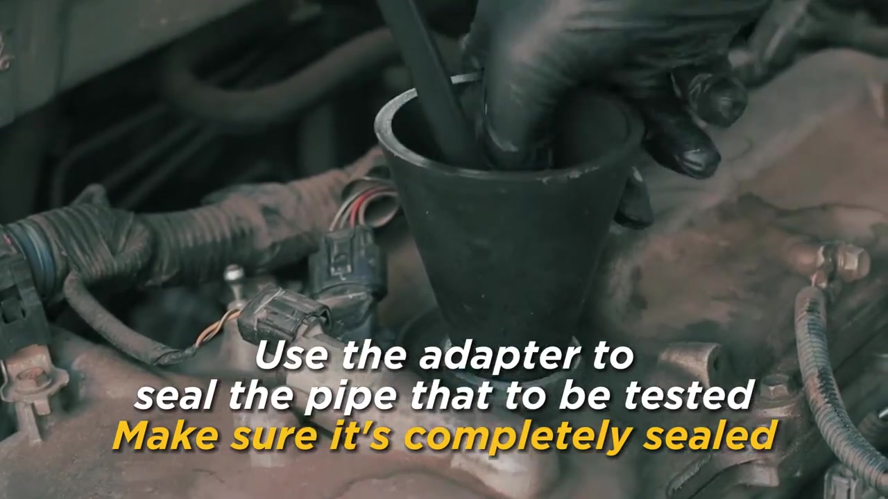
Connect the EVAP adapter or specified line fitting at the approved access point. If a cone or inflatable adapter is used, support it squarely and prove that it does not leak around the perimeter. Cap any intentionally opened branch exactly as the procedure requires.
Use the scan tool or prescribed mechanical method to close the vent and set the purge valve state. The leak test cannot be interpreted until those valve positions are known.
Step 6: Start in Air Mode at minimum controlled flow
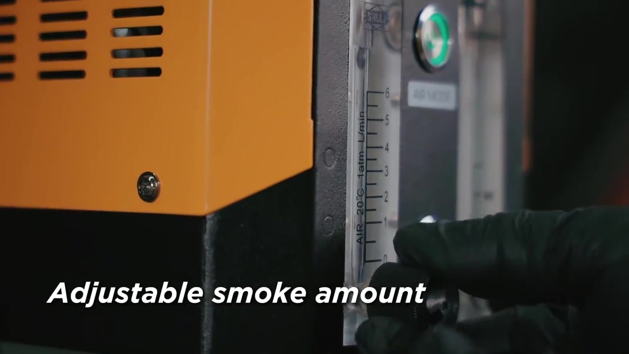
Open the flow control conservatively and switch on Air Mode. Increase only enough to reach the vehicle-authorized test condition. Watch the pressure gauge and flow meter together: pressure response shows whether the boundary fills, while continuing flow suggests an escape path remains.
Never chase the machine’s less-than-18-psi output rating. It is not an EVAP target. Stop increasing flow when the vehicle procedure’s pressure is reached or if a component distorts, whistles or behaves abnormally.
Step 7: Perform a brief pressure/flow hold
Once the system reaches its controlled condition, hold the same valve states and observe whether pressure remains stable and flow falls toward the expected sealed behavior. Record the result and duration rather than deciding from one pointer movement.
A dropping gauge or persistent flow can indicate a system leak, an open commanded valve or a test-adapter leak. Recheck the adapter and caps before moving to Smoke Mode.
Step 8: Switch to Smoke Mode without changing the boundary
Keep the hose, adapter and EVAP valve states unchanged. Activate Smoke Mode and allow the unit to produce smoke. The product record says smoke can begin in about five seconds, while system fill time depends on volume; do not assume 30 seconds is enough for every vehicle.
Adjust the flow only to maintain the permitted pressure and useful visibility. Excess output can hide the first leak in a cloud and unnecessarily stress the system.
Step 9: Inspect from the connection outward
First inspect the SDT206 hose, adapter and any cap you installed. Then follow the EVAP path through the purge connection, vapor lines, canister, vent valve, filler neck, tank seams and accessible fittings. Use a light and mirror for the top of the tank and hidden line clips.
Look for the first repeatable wisp at a specific point. Smoke collecting beneath the vehicle may have travelled from somewhere higher; trace it to the origin before naming a failed part.
Step 10: Subdivide the system if smoke is not decisive
If pressure/flow indicates a leak but no origin is visible, isolate one branch at a time according to the diagram. Repeat Air Mode first on the smaller boundary, then apply smoke. A result that changes after a branch is capped narrows the fault without increasing pressure.
Inspect components that may leak internally into another path, and use the vehicle’s electrical/command tests for purge and vent valves. A valve can fail functionally without producing an obvious external plume.
Step 11: Stop, vent and restore the system
Keep each run within the manual’s recommended duration and stop if the fault/temperature protection activates. Switch Smoke Mode and Air Mode off, allow the test boundary to vent safely, then disconnect the adapter without pulling a vehicle hose sideways.
Restore every factory line, cap and connector. Command valves back to normal, clear only codes addressed by the repair, and run the required leak monitor or service-bay verification. Drain remaining test oil before long storage as the manual directs.
How to interpret air and smoke together
The strongest conclusion comes from agreement between pressure/flow behavior and a localized visual path.
| Air Mode result | Smoke result | Interpretation |
|---|---|---|
| Pressure holds; flow stabilizes low | No external smoke | Test boundary appears sealed under this condition |
| Pressure falls or flow persists | Smoke exits one point | Localized external leak within the boundary |
| Pressure cannot build | Smoke exits at adapter or cap | Repair test setup and repeat |
| Leak indicated | No visible smoke | Subdivide system; inspect hidden or internally leaking valve paths |
EVAP systems are designed for low-pressure vapor control. Use only the vehicle-authorized pressure and valve state. The SDT206 machine output rating is not permission to apply that pressure to an EVAP system.
Common mistakes
- Starting with smoke before proving the adapter and valve states.
- Treating less than 18 psi as an EVAP test target.
- Overfilling oil or refilling while the unit is hot/running.
- Ignoring smoke at the test adapter and blaming the vehicle.
- Increasing flow until the entire area is obscured.
- Calling the first visible smoke accumulation the actual leak origin.
Frequently asked questions
Should I use Air Mode or Smoke Mode first on SDT206?
Use Air Mode first to establish the sealed boundary and observe permitted pressure/flow behavior, then Smoke Mode to localize the escape path.
How much smoke oil does SDT206 need?
The manual directs a 10–15 mL fill. Do not exceed the indicated amount or add oil while the unit is running.
What EVAP pressure should I use?
Use the exact vehicle service specification. Do not use the machine’s rated output pressure as the test target.
Why does Air Mode show leakage but I see no smoke?
The leak may be hidden, internal through a valve, or outside the current visual access. Verify the setup, then subdivide the system while keeping pressure controlled.
Can SDT206 test an automotive A/C system directly?
No. It is a low-pressure smoke detector and is not a direct high-pressure refrigerant-circuit tester.
EVAP test record
- Codes, fuel level, ambient conditions and diagram recorded.
- Exact test boundary and purge/vent states identified.
- SDT206 oil level, 12 V polarity, hose and adapter verified.
- Vehicle-authorized pressure used in Air Mode.
- Pressure/flow behavior documented before smoke.
- Visible leak traced to its true origin or boundary subdivided.
- All factory lines and controls restored and monitor verification completed.
Using SDT206 as a two-stage instrument makes EVAP diagnosis more efficient: Air Mode tells you whether the boundary behaves like a sealed system, and Smoke Mode shows where the escaping flow goes. Control pressure, preserve valve states and let both observations support the repair decision.






Comments 0
Questions, fixes, and real-world diagnostic notes from readers.
Be the first to share a diagnostic result or ask a follow-up question.