
How to Set Up AUTOOL EM365 Voltage Support for ECU Programming

An ECU flash can fail when vehicle voltage dips during a high-load moment or rises outside the programming tool’s permitted window. The AUTOOL EM365 programming power supply can support the installed 12-volt battery while a separate diagnostic system performs the flash. The safe setup is simple in principle: begin with a charged battery, match the exact required voltage, eliminate avoidable loads and monitor the entire session.
Quick answer: With EM365 output off, connect red to the approved positive point and black to the vehicle’s approved negative point, verify the delivered unit’s mains rating, then select Programmable Power Supply. Choose fixed 14.0 V only when the OEM procedure calls for it; otherwise set Adjustable Mode to the exact required value within 10.8–16.0 V. Start support, confirm stable voltage, run the separate programming process, and press Stop only after that process finishes.

In this guide
What EM365 does during ECU programming
EM365 supplies controlled electrical support to the vehicle battery and electrical network. A separate laptop, pass-through device or diagnostic scanner communicates with the ECU and executes the approved file, sequence and recovery logic.
Voltage support reduces one major risk, but it cannot make an incompatible calibration, interrupted network, unstable laptop or incorrect vehicle preparation safe. Treat the programming procedure and power-support procedure as two coordinated checklists.
| Programming-support item | EM365 boundary | How to use it |
|---|---|---|
| Fixed mode | 14.0 V | Select only when the vehicle procedure specifies 14.0 V support |
| Adjustable mode | 10.8–16.0 V | Enter the exact written target before output |
| Maximum programming output | 150 A for approximately three minutes | Not a continuous rating; plan vehicle load below the sustainable boundary |
| Thermal behavior | Output can be limited to 50 A at 70°C until cooling to 50°C | Keep ventilation clear and watch temperature/load behavior |
| Battery condition | Fully charged before programming support | Do not use support mode to hide a weak or discharged starting point |
For charging, restoration, vehicle-display and forced-start functions outside this task, use the complete EM365 operating guide. This procedure stays inside Programming Power mode.
Before you start
- Obtain the exact OEM programming procedure, required voltage, estimated duration and recovery path.
- Fully charge and assess the installed 12-volt lead-acid battery before the session.
- Confirm the programming interface, laptop and software are ready, licensed and connected to reliable power.
- Read the EM365 nameplate and match its mains input, grounded outlet and circuit protection.
- Inspect the housing, fan, output connector, cable and clamps; remove damaged equipment from service.
- Work in a dry, ventilated area and know the locations of Stop and the emergency-stop control.
Do not begin a flash when the correct programming voltage is unknown. A value that worked on another model, battery or module is not a substitute for the current vehicle procedure.
EM365 setup for a programming session
Step 1: Read the programming procedure before connecting
Record the target support voltage, ignition state, door and hood conditions, modules involved, expected time and instructions for loads such as lights, climate control and cooling fans. Confirm whether the procedure permits a support supply at the battery or specifies remote terminals.
Identify the recovery instruction for a communication or power interruption. Do not start merely because the download is ready; both the vehicle and support plan must be complete.
Step 2: Establish a healthy starting battery
Charge and test the vehicle battery by the approved method before entering Programming Power mode. The EM365 manual explicitly calls for a fully charged battery. Support current should handle changing vehicle demand, not compensate for an unknown, deeply discharged or internally failing battery.
Inspect posts, remote terminals, ground paths and battery cables. Excess resistance at a connection can create a voltage drop at the module even when the EM365 display appears stable.
Step 3: Prepare the vehicle and programming equipment
Stabilize the vehicle, control keys and access, and disable only the loads the OEM procedure allows. Keep required network modules awake exactly as directed. Connect the programming interface and confirm that the laptop will not sleep, update or lose its own power during the task.
Route programming and EM365 cables so a technician cannot pull a clamp while reaching the cabin. Keep leads away from fans, belts, sharp edges and hood-latch points.
Step 4: Place and inspect the EM365
Set the unit on a dry, stable surface away from battery gases, conductive debris and vehicle movement. Keep the inlet and cooling fan unobstructed. Verify the delivered nameplate against the grounded mains outlet; regional input versions exist, so do not assume universal input.
Leave the rear switch off and mains disconnected while attaching the output cable. Seat the connector fully and separate the clamps before approaching the vehicle.
Step 5: Connect the clamps with output off
Use the vehicle procedure to identify the approved positive and negative connection points. Attach red to positive and black to the approved negative point. Make clean metal contact, keep your face away from the battery and check that neither clamp can rotate into adjacent metal.
If polarity, terminal identity or cable condition is uncertain, stop. Never energize the unit to see whether an uncertain connection will be accepted.
Step 6: Power on and clear every warning
Connect verified mains, switch on at the rear and allow the initial screen to load. Confirm there is no reverse-polarity, battery-not-connected, temperature, emergency-stop, input or output protection message.
An alert is a diagnostic gate, not a prompt to retry repeatedly. Correct an observable external cause with output off; isolate the unit if the alert remains unexplained.
Step 7: Select Programming Power and the correct voltage
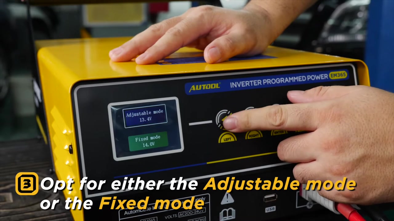
Choose Programmable Power Supply. Select Fixed Mode only when the written requirement is 14.0 V. For any other permitted target, choose Adjustable Mode, use the left/right controls to enter the exact value within 10.8–16.0 V and confirm it.
Do not raise voltage in an attempt to gain more current. Voltage is a compatibility requirement; demand is determined by the vehicle loads that remain active.
Step 8: Start support and prove stability before flashing
Confirm the on-screen battery and connection prompt, then start output. Observe voltage and current while the vehicle is placed in the pre-programming state. Give the system enough time to show that clamps, mains and vehicle demand are stable before selecting Start or Program in the separate tool.
If normal preparation already drives EM365 near its short-duration maximum, do not assume it can sustain the full flash. Recheck unnecessary loads, battery condition and suitability first.
Step 9: Monitor support and programming together
Remain at the vehicle with both displays visible. Watch EM365 voltage, current, temperature behavior, cables and warnings while also following every prompt from the programming system. Prevent doors, lights or climate functions from creating unplanned load changes.
The manual describes 150 A maximum output for approximately three minutes and thermal reduction to 50 A at 70°C internal temperature until cooling to 50°C. Treat falling available current or rising temperature as a reason to follow the programmer’s safe stop/recovery instruction—not to change voltage mid-flash.
Step 10: Finish the flash before ending support
Wait for the programming tool to report a definite completion or to enter its prescribed recovery state. Carry out required ignition cycles, module scans or verification while the support supply remains active if the OEM procedure calls for them.
When the programming procedure says vehicle support can end, press Stop on EM365 and confirm active output has ceased. Do not pull a clamp or mains plug to end normal output.
Step 11: Disconnect and document the session
Remove the clamps in the order specified by the vehicle procedure, switch off the rear mains control and unplug the supply. Inspect the terminals and leads for heat or movement, restore covers and vehicle settings, then complete a full fault scan.
Record target voltage, observed minimum/maximum voltage, peak current, warnings, programming result and post-flash verification. That record distinguishes a stable electrical session from a software or communication problem.
How to judge programming-support quality
A successful flash is the final outcome, but the support record should also show whether electrical conditions stayed controlled.
| Observation | Meaning | Action |
|---|---|---|
| Voltage stable at required target | Support setup and load margin were adequate | Complete programmed-function checks |
| Current spikes but voltage remains controlled | Vehicle demand changed within available support | Record peak and confirm no thermal warning |
| Voltage drifts or warning appears | Connection, mains, battery or capacity margin is inadequate | Use the programmer’s safe stop/recovery path |
| Output is stable but programming fails | Electrical support is less likely to be the cause | Investigate file, interface, network and procedure evidence |
Never change clamps, voltage mode or target voltage while ECU programming is active. If support becomes unsafe, follow the programming system’s documented interruption or recovery procedure and use EM365 Stop or emergency stop as conditions require.
Common mistakes
- Treating EM365 as the device that programs the ECU.
- Starting with a discharged or unassessed vehicle battery.
- Choosing fixed 14.0 V because it is convenient rather than specified.
- Assuming 150 A is available continuously for any length of session.
- Blocking the fan or ignoring thermal current reduction.
- Pulling a clamp before the programming tool has completed its verification.
Frequently asked questions
Does AUTOOL EM365 program an ECU?
No. It supports vehicle voltage. A separate approved scanner, pass-through interface or programming system performs ECU communication and flashing.
Should I use Fixed or Adjustable Mode?
Use Fixed Mode only for a written 14.0 V requirement. Use Adjustable Mode for the exact permitted target between 10.8 and 16.0 V.
Can EM365 support a weak battery during programming?
The manual requires a fully charged battery before programming support. Diagnose or replace an unsafe or failing battery before the flash.
Is the 150 A programming output continuous?
No. The manual describes the maximum for approximately three minutes and also documents thermal current reduction.
When can the clamps be removed?
Only after the programming procedure has completed its required checks, EM365 Stop has ended output and the vehicle procedure allows disconnection.
ECU programming support checklist
- Exact target voltage and recovery path recorded.
- Vehicle battery fully charged and terminals sound.
- Programming laptop/interface prepared and independently powered.
- EM365 nameplate, mains earth, ventilation, leads and polarity verified.
- Correct fixed or adjustable voltage displayed before output.
- Both EM365 and programming screens monitored throughout.
- Output stopped only after flash and verification finished.
- Voltage/current/warning record saved with the programming result.
Reliable ECU programming support is a preparation discipline, not a high-current contest. Start with a healthy battery, use the voltage the vehicle requires, preserve connection integrity and leave support active until the programming system has finished every required check.








Comments 0
Questions, fixes, and real-world diagnostic notes from readers.
Be the first to share a diagnostic result or ask a follow-up question.