
How to Install and Use the MRCARTOOL M60 GPS Inclinometer

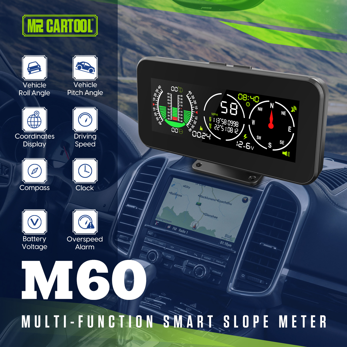
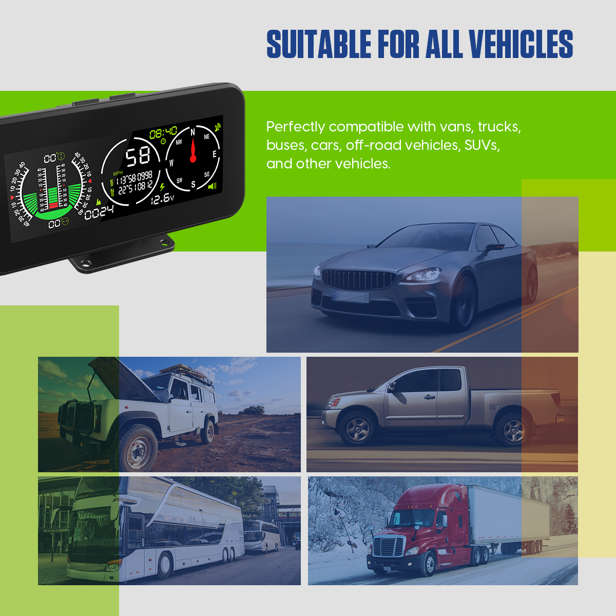
The MRCARTOOL M60 GPS inclinometer combines pitch, roll and input-voltage fields with satellite speed, altitude, direction, coordinates and time. It is useful only when two references are correct: the case must be mounted rigidly and square with the vehicle for meaningful angles, and the receiver must have a stable open-sky GPS fix for meaningful navigation data. Configure units, overspeed warning, speed compensation and time correction while parked, then verify the display before treating it as supplementary driving information.
Quick answer: Dry-fit M60 low on a rigid dashboard surface outside road, instrument and airbag zones. Align it horizontally and square with the vehicle centerline. Use the supplied cigarette-lighter lead first, or have a qualified installer connect the hardwire lead to a correctly fused DC 10–30 V switched circuit. Start outdoors while stationary and allow up to the stated 32-second average cold-start reference; a warm restart may be faster. Long-press the function-select button to enter unit, overspeed, speed-compensation or time-compensation settings; short-press to change the displayed parameter, then long-press the On button to save and exit. Short-press function select outside that menu to adjust brightness. Verify speed and angle behavior safely before use.
In this guide
Understand the M60 fields and limits
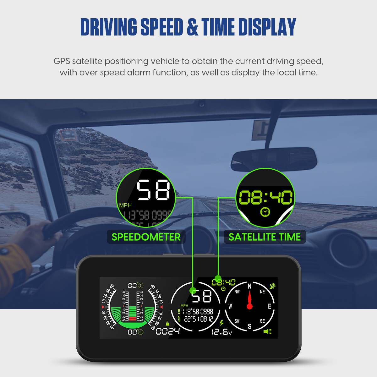
The exact product page specifies DC 10–30 V supply and voltage measurement, 0.5 V stated voltage accuracy, -40°C to 80°C operating temperature and -40° to +40° pitch and roll display ranges. It lists speed accuracy below 0.36 km/h, a one-second GPS refresh rate, average one-second hot start and average 32-second cold start. Those figures describe the instrument under suitable conditions; mounting, signal geometry, update timing and the comparison method still affect what the driver sees.
Pitch and roll come from the M60’s multi-axis gyroscope, while speed, altitude, direction, coordinates and time depend on satellite reception. The voltage value is measured at the M60 supply. Keep these evidence paths separate: a tunnel can interrupt GPS while angle and input voltage remain visible; a loose bracket can corrupt angles while satellite speed still looks plausible; socket voltage drop can affect the voltage field without changing GPS.
The ±40° display span is not a safe vehicle slope. M60 cannot measure tire grip, center of gravity, wheel lift, hidden terrain or rollover margin. Never drive toward a displayed angle or beep to test it. Follow vehicle limits, route conditions and trained spotting practice, keep occupants restrained and turn around before stability is uncertain.
Mount and power the M60
1. Dry-fit a safe rigid location
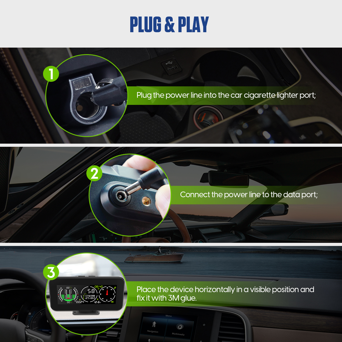
Choose a low dashboard location that can be read with a brief glance but does not block the road, warning lamps, required instruments or vents. Keep the case, holder and cable away from steering-wheel, passenger and curtain-airbag deployment areas. Check glare at night and sunlight during the day. The official installation graphic says to place the device horizontally; use fixed vehicle references to make the face square with the centerline rather than relying on appearance alone.
Tighten every holder joint and press the case lightly from several directions. A rigid mount should not rotate or flex relative to the vehicle. A unit yawed left or right mixes pitch and roll, and a loose ball joint turns vibration into false angle changes. Do not cut the case or modify airbag trim to make it fit.
2. Start with the cigarette-lighter lead
Confirm the outlet is compatible with DC 10–30 V and determine whether it is switched or permanently live. Route the supplied cable along fixed trim away from pedals, steering, shifter, seat tracks, sharp edges and heat. Use strain relief at the display. Verify key-off behavior; if the outlet stays live, do not assume the M60 will shut down soon enough to prevent battery drain.
3. Hardwire only through a qualified protected circuit
The package also contains a refitted power cable, but that is not permission to tap an arbitrary wire. A qualified installer should use the vehicle diagram, correct fuse protection, polarity, conductor sizing, abrasion protection and ground point. Never connect to restraint, data-network or high-voltage circuits. Confirm operating voltage and parasitic current after installation.
Acquire a stable GPS fix
4. Start outdoors while stationary
Park with a broad view of the sky, power the M60 and wait. The page’s 32-second cold-start and one-second hot-start values are averages rather than deadlines. A unit moved a long distance, stored without power or started below a metal roof can take longer. Do not change speed compensation because the first few values are absent or unstable.
Check that satellite time, direction and speed behavior become plausible. A stopped speed of zero alone is not proof of a full fix. Direction can depend on vehicle movement and may be unreliable while stationary. Altitude is especially sensitive to satellite geometry and should be treated as a trend rather than survey-grade elevation.
Configure units, alarms and compensation
The exact page lists five configurable functions: driving unit, overspeed alarm, speed compensation, negative time compensation and positive time compensation. Long-press the function-selection button to enter the setting interfaces, short-press it to adjust the current parameter, and long-press the On button to save and exit. Make every change while parked and record the starting value before adjustment.
5. Set the driving unit first
Confirm km/h or mph before judging speed or entering an alarm. An accurate number interpreted in the wrong unit is dangerous. After saving, cycle power and verify the unit persists. Keep road-sign units and fleet policy aligned with the display.
6. Set the overspeed warning
Choose a threshold appropriate to applicable rules and operating policy, not as authorization to drive at that speed. The M60 cannot see temporary limits, weather, surface grip or tire restrictions. Test the menu and sound without accelerating toward the threshold; use a safe parked configuration check and later observe normal operation.
7. Adjust speed compensation only after comparison
On a safe open road, have a passenger record M60 and a trusted reference while a qualified driver holds a steady legal speed. Compare after both stabilize. Repeat at more than one speed. If a consistent offset remains, stop, enter the menu and make one small documented compensation change. Recheck the same conditions. Do not chase brief differences during acceleration, braking, curves or signal reacquisition.
8. Correct satellite time carefully
Use the negative or positive time-compensation interfaces only after the receiver has a stable fix and the direction of the offset is known. Account for time zone and daylight-saving rules. Make one change, save and compare with a trusted clock. A stable whole-hour offset is usually configuration; a time field that will not stabilize may indicate reception.
9. Set brightness outside the settings menu
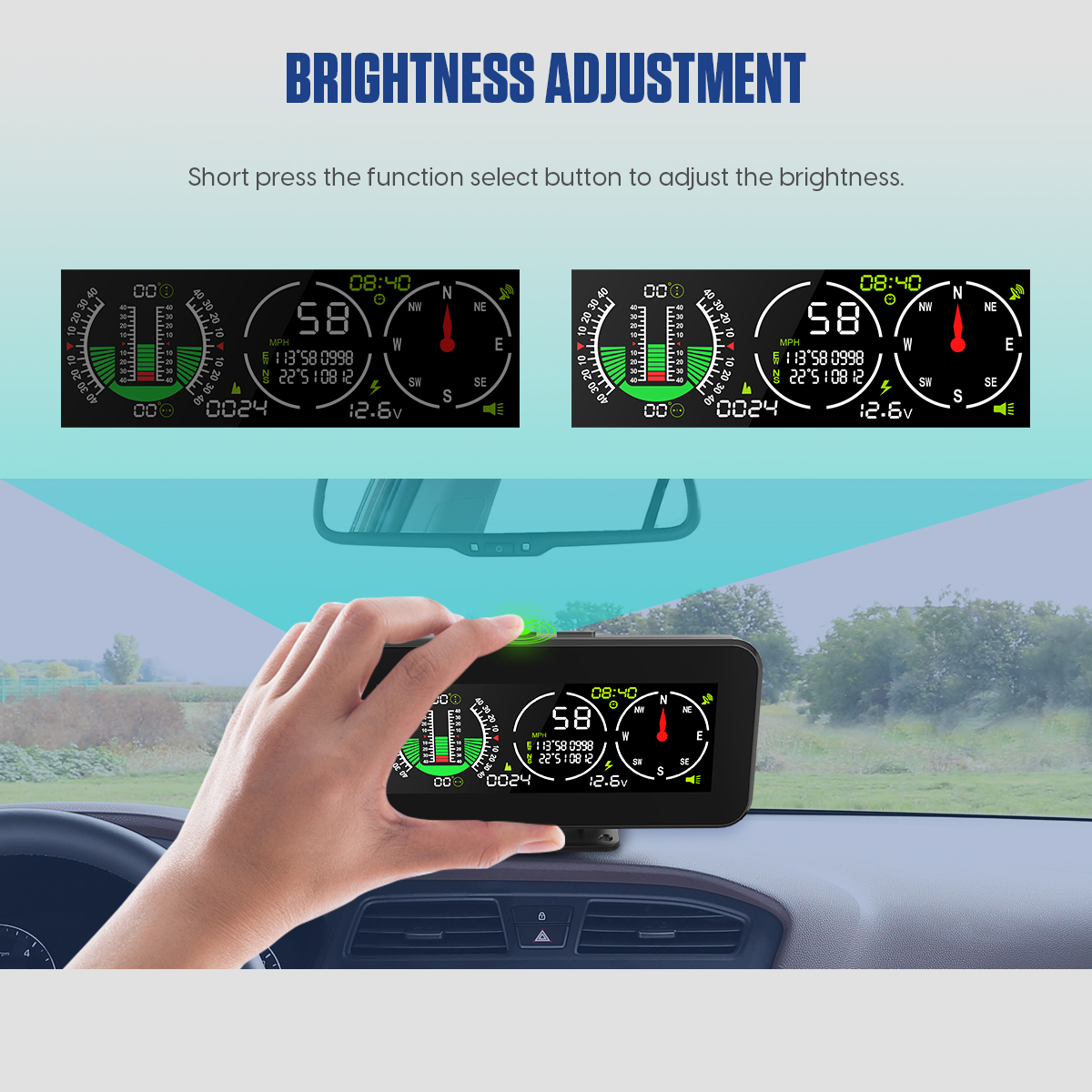
The product page states that a short press of the function-select button adjusts brightness. Do this while parked and after leaving other parameter screens. Choose the lowest comfortable night setting that stays readable; bright windshield reflections can hide external hazards.
Verify pitch, roll, speed and voltage
10. Establish the angle reference
Use a verified level, firm surface with normal tire pressures, ride height and cargo. Let self-leveling suspension settle. Because the retained page does not publish a zero-button sequence, do not borrow one from M50 or another model. Follow the exact included printed manual and current on-screen labels if calibration is required. Confirm the mounted display reads a plausible baseline and that its holder has not moved.
11. Confirm axis direction
Under a controlled, mild condition, confirm nose-up/nose-down and left/right fields respond in the expected direction, then return near baseline on the reference surface. If pitch appears during a pure side tilt or roll changes strongly during straight incline, realign the case. Dynamic acceleration, braking, cornering and bumps add body motion; use stable readings for static-slope assessment.
12. Interpret voltage as a local trend
The screen reads voltage at its own supply path. A cigarette-lighter socket, fuse, connector and cable can introduce voltage drop, so a value may differ from a calibrated meter at the battery. Use it to notice trends or gross supply changes. Diagnose starting and charging faults with the vehicle procedure and suitable test equipment rather than one dashboard number.
Troubleshooting
| Symptom | Check first |
|---|---|
| No power | Outlet state, DC 10–30 V supply, fuse, polarity and cable seating |
| No GPS values indoors | Move outdoors and allow a fresh acquisition with clear sky |
| Speed differs during acceleration | One-second update and comparison-display latency; compare steady speed |
| Angles change after bumps | Bracket movement, dashboard flex, cargo and dynamic body motion |
| Pitch and roll appear mixed | Case rotated relative to the vehicle centerline |
| Altitude seems different from a map | GPS vertical uncertainty, reference datum and current satellite geometry |
| Time is stable but off | Use the correct positive/negative time compensation for local offset |
| Voltage differs from battery test | Socket and wiring drop plus different measurement location |
Final M60 checklist
Recheck the installation after the first trips
Inspect the holder, cable and power connector after the first short road test and again after the first rough-road use. Confirm that no joint has rotated, the cable has not migrated toward a control or sharp edge, and the adhesive or fasteners remain secure. Return to the same level reference and compare the angle baseline; a new offset can reveal bracket movement or a vehicle-load change. Also repeat the key-off check after the vehicle has completed its normal module-sleep period. A display that remains powered, restarts repeatedly or loses saved settings needs its supply path and shutdown behavior corrected before routine use. Record the selected speed unit, overspeed threshold, speed-compensation value and time offset so an unexpected reset can be recognized instead of silently accepted.
- Rigid horizontal mount square with vehicle axes
- Road, instruments, vents and airbags unobstructed
- DC 10–30 V power path fused, correctly polarized and safely routed
- Key-off behavior and battery-drain risk checked
- Stable open-sky satellite acquisition completed
- Driving unit confirmed before speed or overspeed use
- Overspeed threshold configured while parked
- Baseline speed comparison repeated before compensation
- Time correction direction verified against a trusted clock
- Brightness readable without glare
- Angle directions plausible on a controlled mild reference
- ±40° range and beeps never treated as safe vehicle limits
- Voltage treated as supply-path trend, not standalone diagnosis
The M60 is most useful when installation, gyroscope and GPS evidence stay separate. Mount it rigidly and square, protect its power route, acquire satellites in open sky and configure units before alarms or compensation. Verify speed at steady conditions, use altitude and voltage as trends and never convert an angle range into permission to proceed. The vehicle, terrain and driver remain the controlling safety system.






Comments 0
Questions, fixes, and real-world diagnostic notes from readers.
Be the first to share a diagnostic result or ask a follow-up question.