
How to Match and Replace AUTOOL CT Injector Tester Parts

A replacement measuring tube or injector signal connector should restore the machine to its documented configuration—not create a new combination that merely looks compatible. AUTOOL currently asks buyers to identify the CT machine model and confirm the glass-tube scale before ordering. Its CT-series component page also says parts are sold separately and must be confirmed before purchase. Photograph the installed part, match the machine and interface, then replace one controlled item at a time.
Quick answer: For a measuring tube, record the exact CT model, the old tube’s scale, dimensions, mounting points and any machine-version label. For a connector set, match the CT machine output, injector plug and approved electrical interface; physical fit alone is not proof. Drain and isolate the machine before service, protect the glass, reinstall the same routing and seals, then perform a low-risk leak and function check before a full injector test.
In this guide
Identify the part before you open the machine
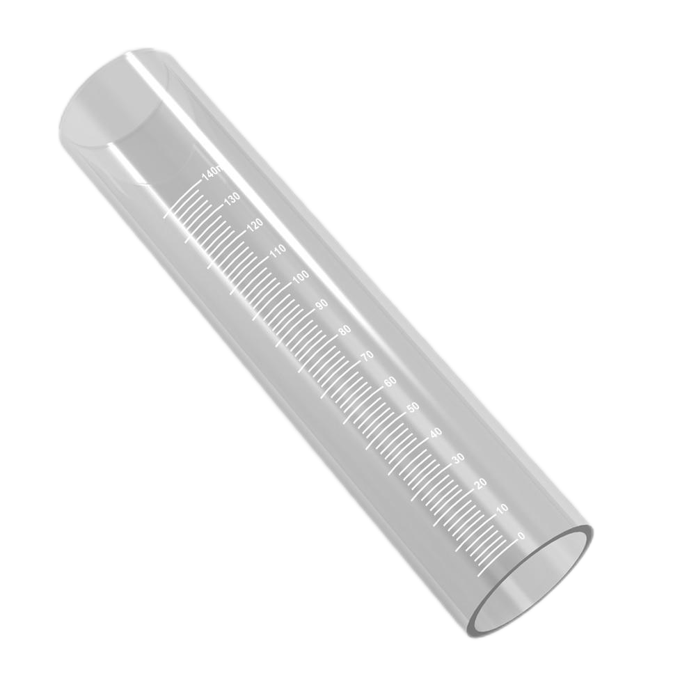
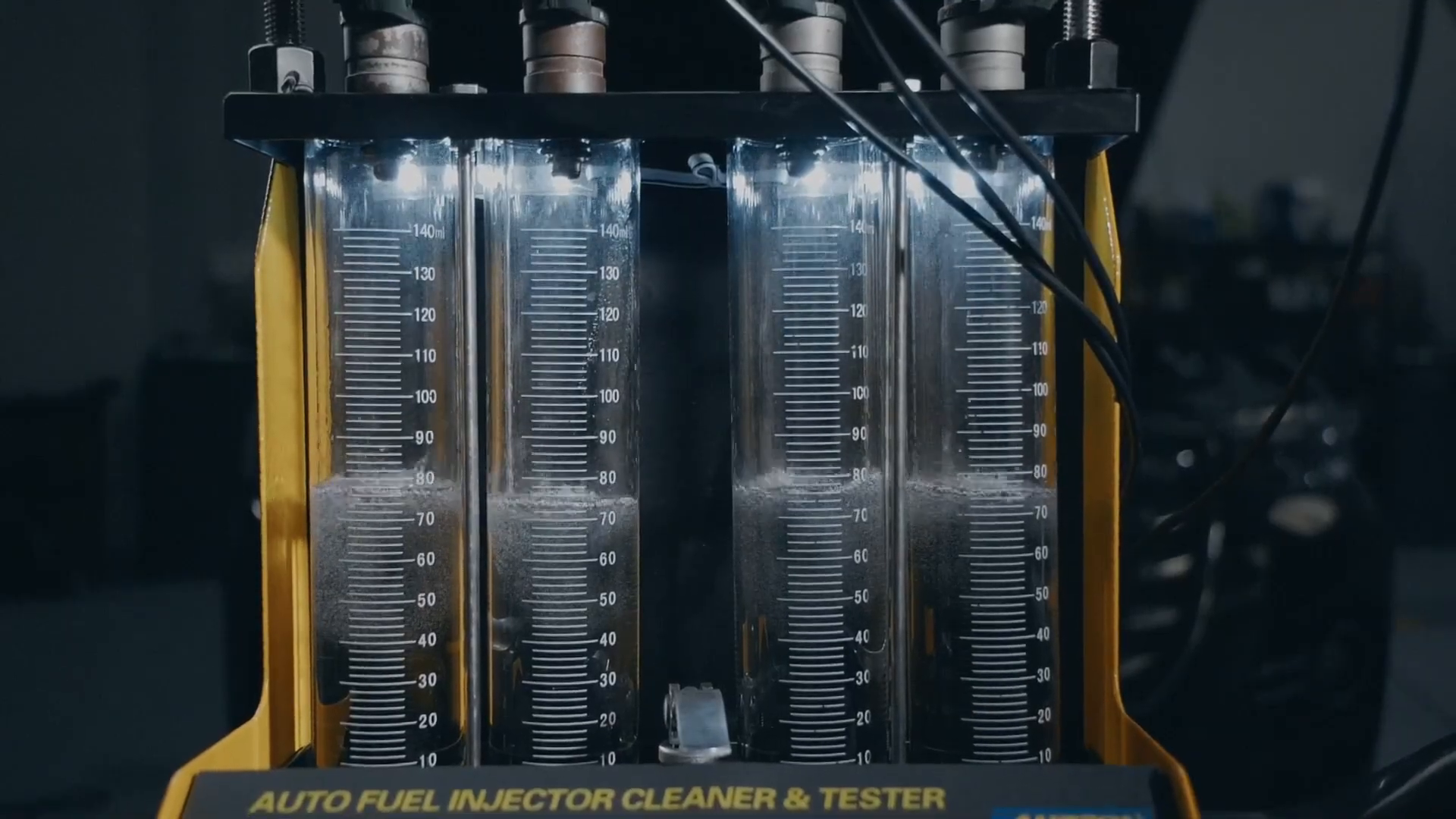
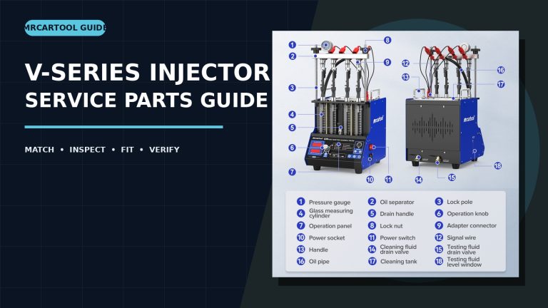
The current AUTOOL glass-tube page covers selected CT150, CT160, CT180, CT200 and CT400 machines and repeatedly asks the buyer to confirm the scale. That is important because two transparent tubes can share a general shape while using different graduations, length, support geometry or production revision. The listed part is a replacement tube only; it is not the complete injector cleaner and tester.
The current CT-series component listing follows the same principle. Components are sold separately, and an image showing several accessories is not a promise that every pictured item is included. Provide the exact model, machine nameplate, installed-part photos and the task the component must perform before ordering.
| Current part reference | Record before ordering | Do not assume |
|---|---|---|
| AUTOOL CT-series replacement measuring tube | CT model, old scale, overall length, mounting points, photos and machine revision. | That a clear tube with similar markings fits or reads correctly. |
| AUTOOL CT-series injector connector and machine parts | Machine model, injector plug face, lead count, machine-side interface and requested quantity. | That a plug that clips onto an injector is electrically compatible. |
Check the delivered machine against the current entry in the AUTOOL manual download center before disassembly. If the exact manual, installed hardware and storefront description disagree, stop and confirm the machine version rather than adapting the new part by force.
Prepare the work area and isolate the tester
The official CT150 quick guide visibly warns that test liquid is flammable and shows eye protection during operation. Work in a ventilated area away from ignition sources, hot surfaces and sparks. Wear suitable eye and hand protection, keep an approved spill response nearby and follow the safety information for the exact test liquid. Do not substitute gasoline or another unapproved fluid.
- Finish or cancel the active program, reduce pressure by the machine’s documented method and switch the tester off.
- Disconnect power and wait for moving or energized functions to stop. Prevent accidental reconnection while parts are exposed.
- Drain the working circuit and measuring area as specified for the machine. Capture fluid in an approved container rather than letting it enter the ultrasonic tank or cabinet.
- Remove the injector rail or fuel distributor only after pressure is released. Mark each hose, signal lead and channel so it can return to the same position.
- Clean the outside of the machine before opening a retainer. Dirt beside a tube seal or electrical connector can create the next leak or intermittent fault.
How to replace an AUTOOL CT measuring tube
Step 1: Document the old tube in place
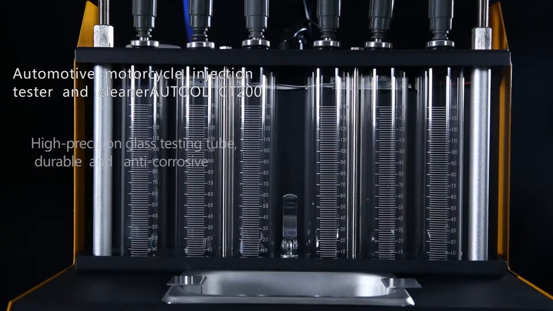
Photograph the complete front rack, the top and bottom supports, scale markings, tube number and adjacent plumbing before loosening anything. Record the machine model and serial or production label. If more than one tube is being changed, label each position so parts and supports cannot migrate between channels.
Check: The old routing, scale and mounting arrangement can be reconstructed from your photos.
Step 2: Compare the replacement beside the old part
Without installing it, compare overall length, outside diameter, wall and end geometry, graduation direction, maximum scale, zero location and support contact points. The current product page explicitly requires scale confirmation. Do not transfer a scale label or modify a bracket to make a different tube appear correct.
Check: Every functional dimension and the scale agree with the confirmed replacement specification.
Step 3: Release the tube without loading the glass
Support the tube with one hand while releasing only the retainers described for the exact tester. Avoid twisting, levering against the scale or letting the tube carry the weight of a rail or hose. Keep removed seals, spacers and clamps in order. If the tube is chipped or cracked, contain fragments and do not handle broken edges bare-handed.
Check: The tube is removed without damage to the supports, plumbing or neighboring channels.
Step 4: Inspect supports, seals and fluid paths
Look for hardened or swollen seals, corrosion, cracked supports, residue and misalignment. A new tube will not fix a bent bracket or leaking fitting. Replace seals only with the type specified for the machine and test fluid; do not use general-purpose tape, adhesive or sealant on a joint not designed for it.
Check: Mating surfaces are clean, aligned and undamaged, and the correct seals are available.
Step 5: Install and align the confirmed tube
Orient the graduation scale to the same readable position as the original, seat the lower and upper interfaces squarely and reinstall retainers in the documented order. Tighten only to the current instructions. Glass needs support, not crushing force. Verify that hoses and fittings are not side-loading the tube.
Check: The tube is straight, supported, readable and free from point loads or forced connections.
Step 6: Check the empty assembly
Before adding fluid, compare the replaced channel with the untouched channels. Confirm equal support height, clearance, hose routing and rail alignment. Gently verify that nothing is loose using the approved inspection method; do not use the tube as a handle.
Check: The channel matches the original layout and no part contacts or stresses the glass.
Stop: Do not pressurize the tester if a tube scale is different, glass is chipped, a support is bent, a seal is unknown, a fitting starts crooked or a hose pulls sideways. Reconfirm the part instead of compensating with extra tightening.
How to match and use CT-series injector connectors
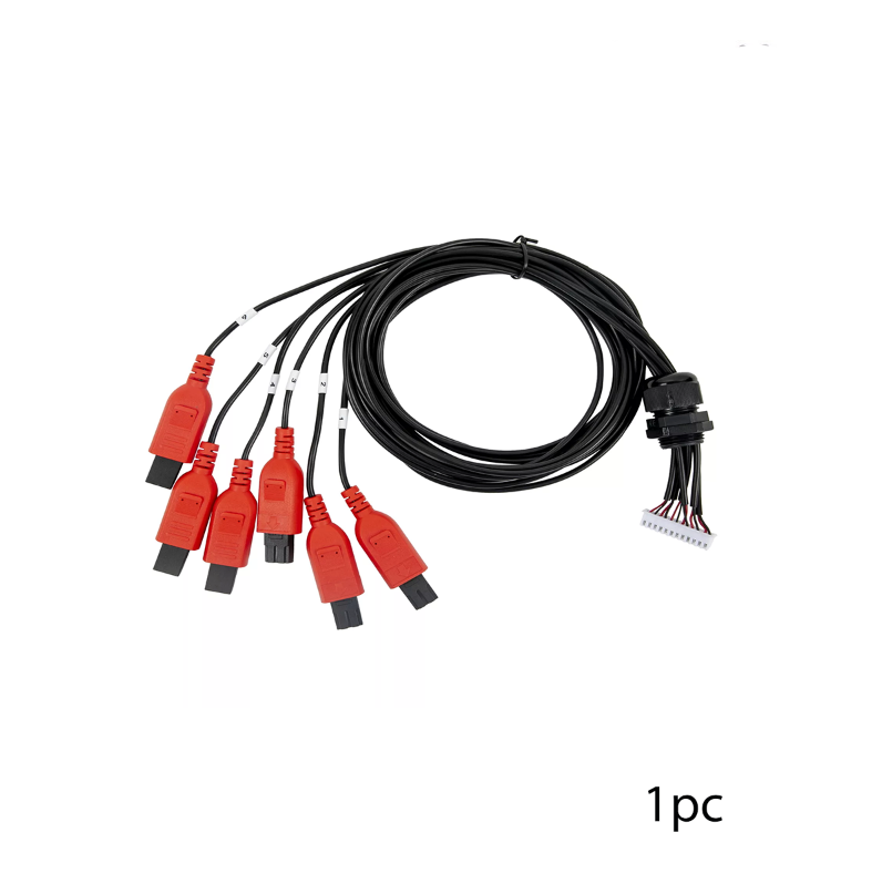
A connector set bridges the tester’s signal output to the injector under test. It does not automatically adapt voltage, current, polarity, waveform or injector type. The current component page tells buyers to confirm the CT model and requested part, while the official CT150 guide shows the signal cable being connected only after the injectors and distributor are secured.
- Identify the injector by application and part number, then inspect the plug face, key, terminal count and latch. Do not select by color alone.
- Confirm that the exact CT machine supports the injector type and that the machine-side harness is the correct accessory for that tester revision.
- With power isolated, inspect every lead for pulled insulation, bent or recessed terminals, corrosion, loose strain relief and previous repair splices.
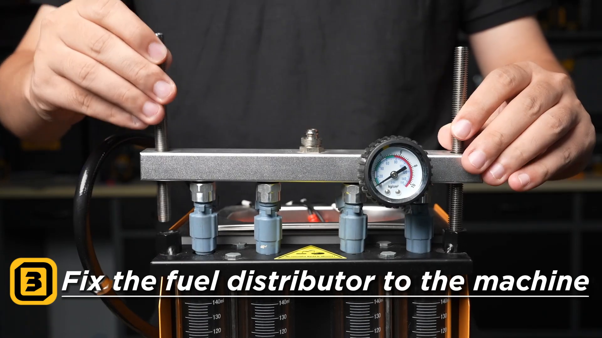
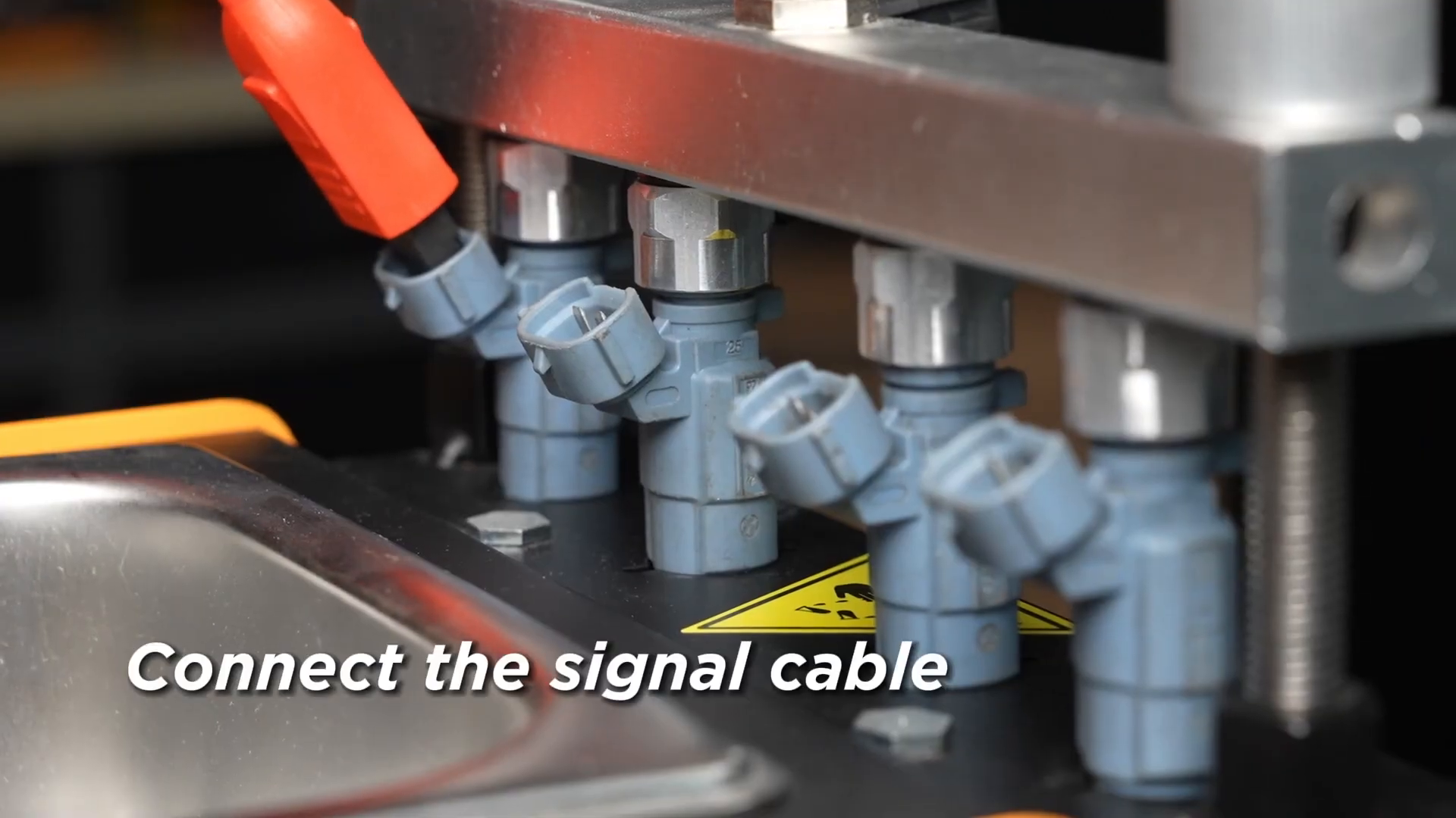
- Mount the injectors and fuel distributor squarely before attaching signal leads. A hanging lead must not carry an injector or pull it out of alignment.
- Connect each adapter by its keyed interface and map the lead to the matching test channel. Never force a latch or bridge exposed terminals.
- Route leads away from the fluid path, ultrasonic tank, sharp edges and hot surfaces. Keep enough slack for strain relief but not enough to enter moving or wet areas.
Run the first controlled leak and function test
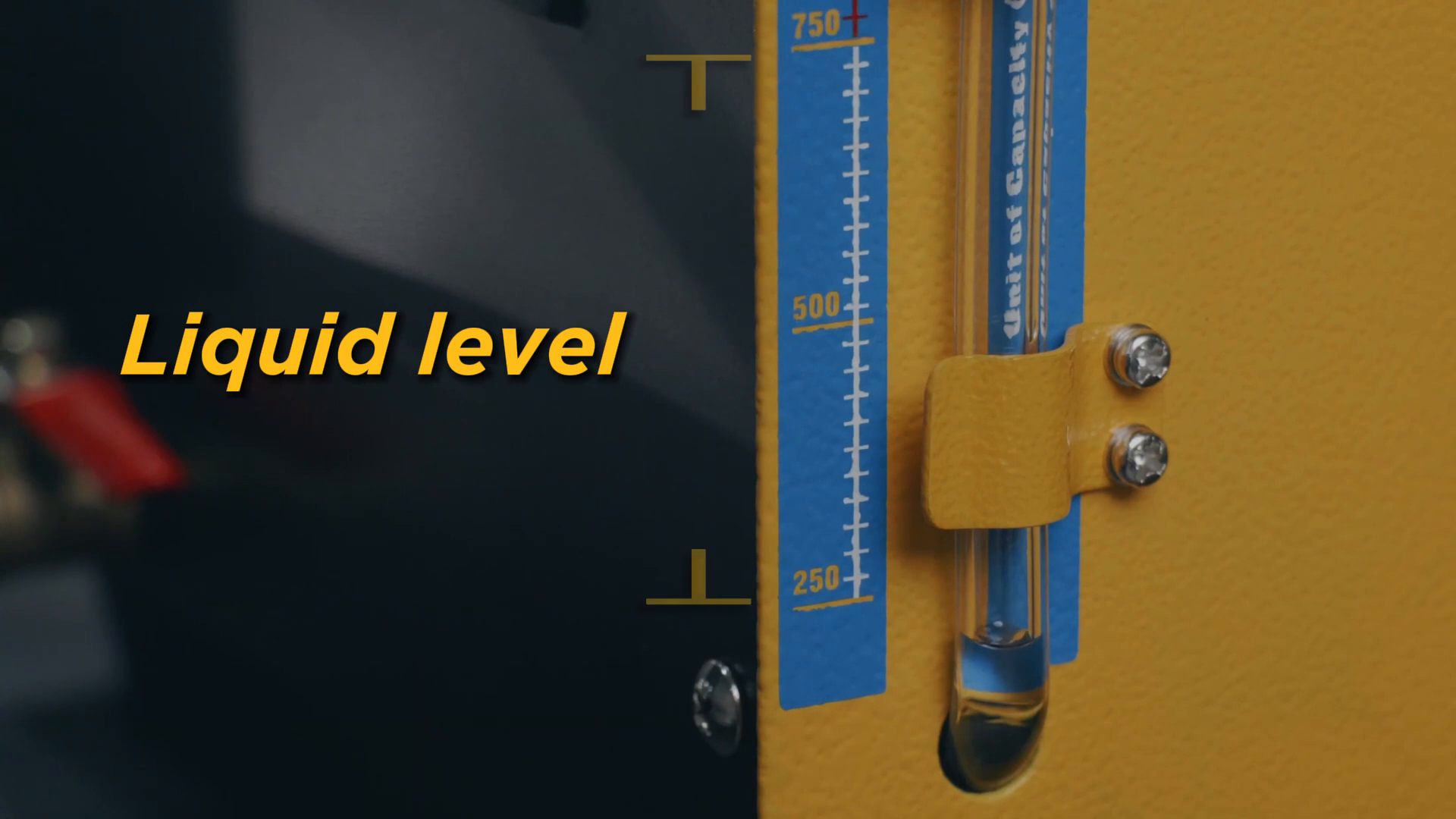
Restore the machine in stages. First confirm that all tools, glass fragments and loose hardware are removed. Reconnect the approved test-fluid circuit and add only the fluid and amount specified by the current machine instructions. The CT150 official video shows checking liquid level, fixing the distributor to the machine, connecting the signal cables and wearing goggles before the visible spray test.
- Power the tester with no active test and check for abnormal display behavior, odor, heat, sound or movement.
- Prime or fill the circuit only by the documented machine sequence. Watch the replaced tube’s top and bottom joints continuously.
- Perform the lowest-risk applicable leak check before a full pressure or flow program. Stop immediately for seepage, bubbles at a joint, tube movement or a falling level.
- Confirm that every injector is mechanically secure and each signal lead stays dry and strain-relieved before enabling a pulse program.
- Run the exact test mode and limits specified for the injectors. Do not use a replacement connector as a reason to increase pulse width, voltage or pressure.
- Compare channel behavior, spray pattern and collected volume using the machine procedure. A new tube must remain leak-free and readable; it does not by itself calibrate the tester or prove an injector is serviceable.
After the test
- Stop the program, release pressure and isolate power before touching the rail, tubes or connectors.
- Drain or store test fluid according to its instructions and local requirements. Clean spills promptly and keep all ignition sources away.
- Wipe the tube with a compatible soft material; avoid abrasives or solvents that can cloud the glass or remove scale markings.
- Inspect connector terminals and strain relief after removal. Dry the leads fully before coiling them loosely in labeled positions.
- Record the installed part, confirmed scale, machine version, replacement date, test result and any seal or support changed at the same time.
Frequently asked questions
Is the replacement tube only for CT150 and CT200?
The current product page also references selected CT160, CT180 and CT400 machines, but it requires the buyer to specify the machine and confirm the scale. Treat each model and production version as a separate fitment decision.
Can I order by the 140 ml description alone?
No. Capacity wording is not enough. Match the printed scale, length, diameter, ends, supports and machine version, and send clear photos when any detail is uncertain.
Can I reuse the old seals?
Only if the exact machine instructions permit reuse and the seals remain the correct type and condition. Hardened, swollen, cut or unknown seals should not be trusted around pressurized test fluid.
Does a motorcycle-injector plug that fits prove compatibility?
No. Mechanical fit does not prove the tester output and injector electrical requirements agree. Confirm the exact CT machine, harness and supported injector type before energizing it.
Should all measuring tubes show exactly the same value?
Use the tolerances and comparison method in the exact tester and injector procedure. Unequal readings can come from injector behavior, air, leakage, setup or a measurement problem; replacing one tube does not identify the cause by itself.
Can gasoline be used as test liquid?
Do not improvise with gasoline. Use only the test or cleaning fluid specified for the exact machine and service task, with the required ventilation, PPE and fire controls.
Final parts checklist
- Exact CT model, machine version and installed part are documented
- Replacement tube scale, dimensions and supports match before removal
- Pressure, power and flammable test fluid are controlled before service
- Tube seals and fittings are clean, square and free from side load
- Connector set matches the tester interface and supported injector—not just the plug shape
- Fuel distributor, injectors and signal leads are secured in the documented order
- Low-risk leak check passes before the full test program
- Replacement and verification details are recorded for the next service
The reliable path is simple: identify the original configuration, isolate the machine, replace like for like and prove the repaired channel at low risk before a full test. That protects the operator, the injector tester and the measurement you are trying to trust.


Comments 0
Questions, fixes, and real-world diagnostic notes from readers.
Be the first to share a diagnostic result or ask a follow-up question.