
How to Use the AUTOOL TR401 Airflow and Temperature Meter

The AUTOOL TR401 is an airflow and temperature meter. This guide turns the current model-specific controls and official operating sequence into a practical start-to-finish workflow.
Quick answer: Set one repeatable HVAC condition, choose and record the wind-speed and temperature units, then hold the TR401 vane square to each outlet at the same distance without blocking the grille. Wait through several 0.5-second updates, record a stable range and outlet temperature, and compare like vents under the same blower, mode, recirculation, engine and door conditions. Use the pattern to choose the next HVAC test; TR401 does not directly measure total CFM or refrigerant condition.
In this guide
Before you start
Automotive vent readings change with fan speed, selected mode, recirculation, cabin pressure, filter restriction, engine speed, ambient temperature and exactly where the vane sits in the air stream. A meaningful comparison controls those variables first. Run an engine only in a properly ventilated area, secure the vehicle and keep the meter clear of moving controls and the driver’s feet.
- inspect the wind wheel for damage, dirt or drag and install three correctly polarized AAA alkaline batteries;
- record ambient temperature plus the vehicle, engine, blower, temperature, recirculation and vent-mode conditions;
- choose one wind-speed unit and °C or °F before starting the outlet map;
- clear old MAX/MIN values and use real-time mode for the baseline measurements;
- mark one repeatable vane distance and orientation that does not block the outlet; and
- prepare an outlet-by-outlet worksheet that keeps velocity, temperature, position and conditions together.
Use the AUTOOL manual download center to locate the current instructions when a manual is available. The delivered model label and current vehicle service information control if an older image or remembered setting differs.
TR401 controls and specifications
| Specification or function | Current model |
|---|---|
| Power Supply | 3 × AAA 1.5V alkaline batteries |
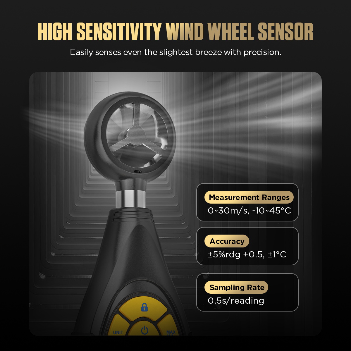
| Wind Speed Range | 0-30 m/s |
| Wind Speed Resolution | 0.1 m/s |
| Wind Speed Accuracy | ±5% rdg + 0.5 |
| Wind Speed Units | m/s, mph, km/h, ft/min, knots |
| Temperature Range | -10°C to 45°C |
| Temperature Resolution | 0.1°C |
| Temperature Accuracy | ±1°C |
| Sampling Rate | 0.5 s per reading |
| Beaufort Scale | 0-12 levels |
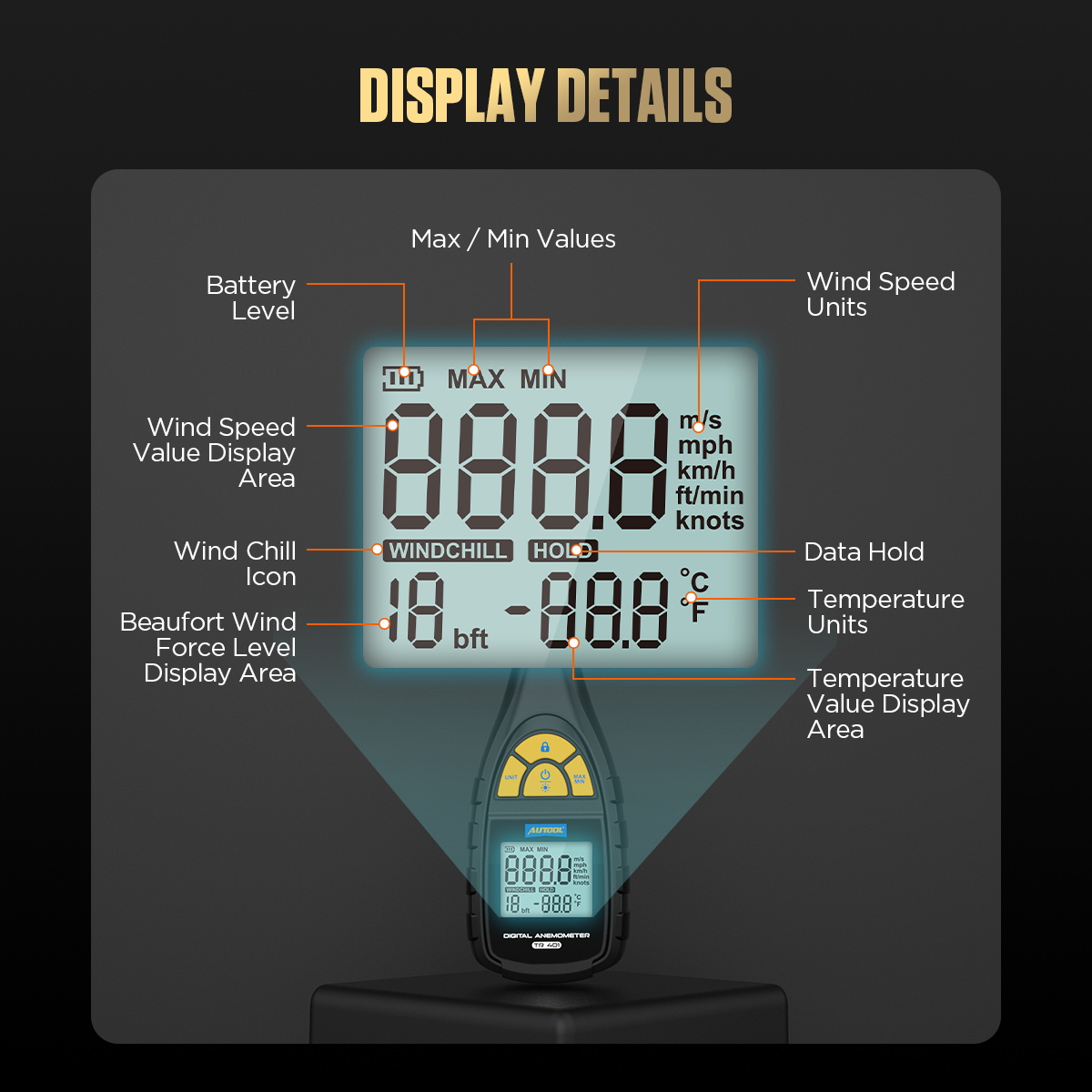
The current manual specifies a 0-30m/s wind-speed range, 0.1m/s resolution, ±5% rdg + 0.5 accuracy, a -10°C to 45°C temperature range, ±1°C temperature accuracy and a 0.5-second sampling interval. Its IP40 enclosure is not a water or refrigerant-fluid rating. The display’s Beaufort and wind-chill functions describe ambient wind contexts; they are not automotive HVAC pass/fail limits.
How to use the TR401
Step 1: Define one repeatable automotive HVAC test condition
Park safely in a ventilated work area and record ambient temperature, vehicle warm-up state, engine speed, fan setting, temperature command, recirculation or fresh-air mode, vent mode, door/window position and which vents are open. Do not compare readings taken under different blower, door or engine conditions.
Before moving on, confirm the engine can run with effective exhaust ventilation and write down every HVAC setting that must remain unchanged during the outlet comparison.
Step 2: Inspect the vane and install three AAA batteries
Make sure the wind wheel rotates freely and is not cracked, dirty or obstructed. Install three 1.5V AAA alkaline batteries using the marked polarity, close the cover and press power. Replace the batteries when the low-battery icon appears.
Step 3: Choose units and clear the previous extrema
Press UNIT to choose m/s, mph, km/h, ft/min or knots; long-press UNIT to choose °C or °F. Use real-time mode for the primary vent reading. Long-press the MAX/MIN key to clear earlier maximum and minimum values so a prior job cannot contaminate this comparison.
Step 4: Stabilize the vehicle and HVAC system
Run the vehicle only with safe exhaust ventilation. Set the documented blower, temperature, recirculation and outlet mode, then allow the airflow and discharge temperature to stabilize. Confirm the cabin filter, vent louvers and selected outlet path are not being changed during the test.
Step 5: Place the vane squarely without blocking the vent
Face the wind wheel directly into the outlet airflow at a fixed distance and orientation. Keep fingers and the meter body out of the air stream as much as practical, and do not press the vane against the grille. Mark or photograph the position so every vent can be checked the same way.
Step 6: Wait for a stable real-time reading
Observe several 0.5-second samples until the wind-speed and temperature displays settle within a narrow repeatable band. Record the range or representative stable value together with the exact unit and HVAC condition; one transient peak is not the baseline.
Step 7: Map every comparable outlet
Repeat the same placement at the center, side and rear outlets that share the selected HVAC mode. Where a vent is large, sample more than one point instead of treating one high-velocity spot as the whole outlet. Preserve outlet name, position, velocity and temperature together.
Step 8: Use HOLD or MAX/MIN only for a defined question
Press HOLD to freeze a stable display for transcription, then release it before the next measurement. Use MAX or MIN to capture variation over one named interval, not as the default result. Clear extrema before changing vents or test conditions.
Step 9: Compare patterns and move to the next diagnostic test
Compare like outlets under the same command and repeat a low or uneven result after checking placement, louvers, filter restriction and selected mode. TR401 measures local air velocity and temperature; it does not directly measure total CFM, refrigerant pressure, charge amount, leakage, actuator command or evaporator condition.
Step 10: Power off, protect the vane and retain the worksheet
Long-press power to switch off, remove the meter from the vehicle and check that no vent louver was damaged. Clean only with a neutral method, protect the wind wheel from impact and store the TR401 dry. Remove batteries for extended storage.
Before closing the HVAC check, repeat the weak or uneven outlet under the original conditions, release HOLD, save the full outlet map and identify the vehicle-specific next test.
Read and verify the result
Read an HVAC outlet map as a controlled comparison. Similar outlets commanded by the same mode should show a coherent airflow and temperature pattern. A repeated weak outlet may direct attention to louver position, duct leakage or obstruction, door travel or distribution; all outlets weak can direct attention to fan command, blower performance, cabin filter or a broad restriction. Temperature differences can guide further HVAC diagnosis, but they do not identify charge, pressure or component condition without the vehicle procedure and appropriate instruments.
- Record a stable range when the value naturally fluctuates instead of selecting one convenient instant.
- Compare center, side and rear outlets only when the selected HVAC mode is intended to supply them.
- A local velocity at one point is not total outlet volume. A CFM calculation needs outlet area and a suitable multi-point average or dedicated method.
- A cold outlet with weak airflow and a strong outlet with warmer air are different symptom patterns and call for different next checks.
- Repeat the same map after a repair with the original conditions preserved; otherwise the before-and-after comparison is weak.
Stop if the vane contacts a vent, the wheel sticks or overspeeds, the meter gets wet, the engine area is not safely ventilated, the vehicle can move, exhaust enters the cabin, or the reading cannot stabilize because the test condition keeps changing. Correct the setup before interpreting the numbers.
Common mistakes and care
- Keep the wind wheel clear of fingers, vent vanes, loose material and compressed-air blasts that can overspeed or damage it.
- Compare vents only under the same fan, mode, recirculation, engine, door/window and placement conditions.
- Do not convert one local velocity reading into total CFM without a suitable area and multi-point traverse method.
- Run an engine only with effective exhaust ventilation; stop for fumes, overheating or unsafe vehicle movement.
- Keep the instrument away from strong electromagnetic radiation, corrosive chemicals and flammable or explosive environments.
- Do not cover part of the outlet with the meter body or change the vane angle from vent to vent.
- Do not compare readings taken at different blower speeds, recirculation states, door positions or engine conditions.
- Do not leave HOLD active and unknowingly copy the same frozen value to the next outlet.
- Do not carry MAX/MIN values from one outlet or job into another; clear them between defined intervals.
- Do not call a local m/s, mph or ft/min reading CFM without a valid area-and-traverse calculation.
Frequently asked questions
Does a TR401 vent reading show CFM?
Not by itself. TR401 reports local air velocity and temperature. Total volume requires a suitable outlet area and representative multi-point average or a dedicated airflow-volume method.
Why do two readings at the same vent differ?
Fan control, recirculation, door position, engine speed, vane angle, distance and the sampling point can all change the result. Fix those variables and record a stable range rather than one instant.
Can TR401 diagnose low refrigerant charge?
No. Outlet temperature and velocity can support an HVAC symptom map, but refrigerant diagnosis requires the exact vehicle procedure and appropriate pressure, temperature, leakage and control-system checks.
Final TR401 checklist
- Wind wheel free and undamaged; battery condition normal
- Vehicle, engine and HVAC operating conditions documented
- Wind-speed and temperature units fixed for the complete map
- Vane distance and orientation repeated without blocking each outlet
- Stable velocity range and temperature saved for every comparable vent
- HOLD released and MAX/MIN cleared between defined tests
- Observed pattern linked to the next vehicle-specific HVAC check
- TR401 powered off, vane protected and worksheet retained
The TR401 is strongest as a consistency tool: control the HVAC state, measure every outlet the same way and preserve the pattern. That turns a handheld wind reading into useful evidence without pretending it replaces airflow-volume, pressure, refrigerant or actuator diagnosis.







Comments 0
Questions, fixes, and real-world diagnostic notes from readers.
Be the first to share a diagnostic result or ask a follow-up question.