
How to Use the AUTOOL TG501 Coating Thickness Gauge

The AUTOOL TG501 is an automotive paint and coating thickness gauge. This guide turns the current model-specific controls and official operating sequence into a practical start-to-finish workflow.
Quick answer: Start the TG501 at least 2cm away from metal, select and record the unit, then zero it on the supplied Fe or NFe reference that matches the panel. Verify the zero with a known film, place the probe squarely on clean flat paint until it beeps, and map several points on every panel. Compare repeated patterns across the same vehicle; one reading alone cannot prove a repaint or collision repair.
In this guide
Before you start
Paint thickness is meaningful only when the contact, substrate, unit and sampling pattern stay controlled. Wash and dry the test areas, let hot panels stabilize, and avoid edges, body creases, fasteners and tight curves. First identify whether each panel is ferromagnetic steel or a non-ferromagnetic metal such as aluminum; plastic and composite panels are outside this Fe/NFe gauge’s measurement principle.
- install three serviceable AAA alkaline batteries with the marked polarity and inspect the spring-loaded probe for dirt or damage;
- prepare the supplied Fe and NFe bare references plus at least one known thickness film;
- choose one reporting unit—µm, mm or mil—and label the inspection sheet before taking the first vehicle reading;
- divide the vehicle into named panels and repeatable measurement zones so every value can be traced to a location;
- note panel material changes, repaired edges, protective film and unusually curved areas before interpretation; and
- keep magnets, large electrical equipment and other strong electromagnetic sources away from the measurement area.
Use the AUTOOL manual download center to locate the current instructions when a manual is available. The delivered model label and current vehicle service information control if an older image or remembered setting differs.
TG501 controls and specifications
| Specification or function | Current model |
|---|---|
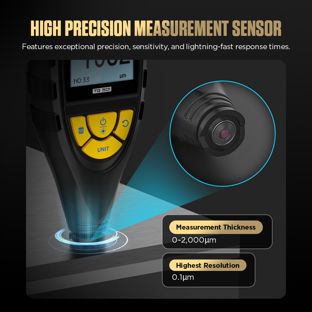
| Measuring Range | 0-2,000 µm |
| Accuracy | ±(3% + 1 µm) |
| Power Supply | 3 × AAA 1.5V alkaline batteries |
| Resolution | 0.1 µm from 0-100 µm; 1 µm above 100 µm |
| Measurement Principle | Fe magnetic induction; NFe eddy-current effect |
| Units | µm, mm, mil |
| Minimum Measurement Area | 15mm diameter |
| Minimum Substrate Thickness | Fe 0.30mm; NFe 0.05mm |
| Maximum Measurement Speed | 2 readings per second |
| Operating Environment | -10°C to 50°C; 20-90% RH, non-condensing |
The manual specifies 0-2,000µm, with 0.1µm resolution from 0-100µm and 1µm resolution above 100µm, plus ±(3% + 1µm) accuracy under its stated conditions. The minimum measurement area is 15mm diameter; minimum substrate thickness is 0.30mm for Fe and 0.05mm for NFe. These are instrument boundaries, not universal factory-paint limits. Vehicle construction, substrate, panel location and production process all affect the baseline.
How to use the TG501
Step 1: Prepare a panel map and a clean measurement surface
Work on clean, dry painted metal at a stable temperature. Divide the vehicle into repeatable zones—roof, hood, fenders, doors, quarter panels, pillars and trunk—and note which panels may be steel or aluminum. Dirt, water, wax buildup, a hot panel, a tight curve or an edge can distort contact and interpretation.
Before moving on, confirm the surface is clean, dry and cool enough for repeatable contact, and mark which panels are Fe, NFe or outside the gauge’s metal-substrate capability.
Step 2: Install three AAA batteries and start away from metal
Fit three 1.5V AAA alkaline batteries using the marked polarity and close the cover. Hold the probe at least 2cm away from any metal object, then press the power/backlight button. Replace the batteries when the low-battery symbol appears.
Step 3: Choose units and the correct probe mode
Press UNIT to select µm, mm or mil and record that unit on the inspection sheet. AUTO is the normal starting mode because the TG501 identifies ferromagnetic and non-ferromagnetic substrates; use MAG only for ferromagnetic metal and EDDY only for non-ferromagnetic metal when a controlled comparison requires a fixed mode.
Step 4: Zero-calibrate on the matching bare substrate
Use the supplied clean Fe or NFe reference that matches the panel substrate. Long-press the probe-mode button until two beeps and ZO appear, place the probe squarely on the bare reference, then wait for 0.000 and the flashing ZO indication. On a rough reference, repeat at several positions before pressing the mode button to exit calibration.
Step 5: Check calibration with a supplied thickness film
Place a known film flat on the matching bare substrate and take several readings near the center. Confirm the results are repeatable and reasonable for that reference before moving to the vehicle. Re-clean, re-zero and inspect the probe if a stable check cannot be obtained.
Step 6: Place the probe squarely and wait for the beep
Lower the probe perpendicular to a flat area at least 15mm across and away from panel edges, body lines, fasteners or extreme curvature. Let the spring-loaded probe retract without sliding it. When the displayed value refreshes and the TG501 beeps, lift it clear before moving to the next point.
Step 7: Measure several points on every panel
Take a consistent grid of readings rather than one spot—typically the center plus representative upper, lower, front and rear areas where accessible. Keep the same unit, mode and contact technique. Record the substrate indication, value and exact panel location for each point.
Step 8: Compare patterns, not one universal paint number
Establish the vehicle's own baseline from multiple coherent panels, then look for abrupt within-panel changes, one panel consistently above adjacent panels, unusually high buildup or an unexpected substrate change. A thickness gauge supports a refinishing hypothesis; it does not by itself prove accident history, filler depth or repair quality.
Step 9: Review or clear stored readings deliberately
Use the power/backlight button as described by the manual to review measurement data. A short press of the delete button removes the latest stored reading; a long press removes all recorded data. Transcribe or photograph needed results before clearing them.
Step 10: Finish the inspection and store the gauge
Repeat any outlier after cleaning the spot and confirming contact, mode and substrate. Long-press power to switch off, wipe the probe and housing with a dry or lightly neutral-cleaner cloth, and store the TG501 and calibration references dry. Remove the batteries for extended storage.
Before closing the inspection, repeat every material outlier after checking calibration, surface cleanliness, probe contact and measurement location, then preserve the panel map before clearing stored data.
Read and verify the result
Interpret a map, not a magic number. A coherent group of panels establishes the vehicle’s baseline. Repeatedly higher values across one complete panel can support a repaint hypothesis; a sharp local peak may support localized repair buildup; an isolated outlier that disappears after cleaning or repositioning is more likely setup noise. Confirm any finding with visual condition, panel gaps, fasteners, seam sealer, repair records and a qualified body inspection.
- Record the substrate indication and unit beside every value; steel and aluminum panels should not be mixed into one unlabeled average.
- Use several readings per panel and repeat outliers at nearby flat points without sliding the probe.
- A stable high reading supports added coating thickness but does not reveal whether the layer is primer, paint, clear coat or body filler.
- A low reading can reflect a thin factory area, polishing, probe contact or substrate geometry; verify technique before escalating the conclusion.
- Plastic bumpers and composite panels do not provide the Fe or NFe metal substrate required by this gauge.
Pause the inspection if the probe will not identify the substrate, readings are unstable on the reference plate, the panel is wet or very hot, the surface is too curved for full contact, the instrument shows overflow or no response, or the vehicle is near strong electromagnetic interference. Correct the condition and recheck calibration before relying on more measurements.
Common mistakes and care
- Keep the probe clean and place it squarely; do not drag it across paint or measure on wet, dirty, very hot or strongly curved surfaces.
- Use the matching Fe or NFe calibration substrate and verify calibration before relying on a vehicle map.
- Do not treat one high or low reading as proof of collision repair; compare repeated patterns with visual, structural and history evidence.
- Avoid strong electromagnetic fields, corrosive chemicals, flammable environments and unauthorized disassembly.
- Do not power the TG501 on while the probe is resting against metal; start it at least 2cm away as the manual specifies.
- Do not zero on a painted vehicle panel; use the matching supplied bare Fe or NFe reference.
- Do not drag the probe, press on an edge or mix µm and mil in the same unlabeled worksheet.
- Do not delete stored readings until required results have been transcribed or photographed.
- Do not market one isolated value as proof of accident history or concealment.
Frequently asked questions
What paint thickness proves that a panel was repainted?
There is no universal threshold for every vehicle. Build a repeated baseline from the same vehicle, substrate and unit, then investigate coherent differences with visual, structural and history evidence.
Can the TG501 measure a plastic bumper?
No. Its Fe magnetic-induction and NFe eddy-current methods require a suitable metal substrate. Plastic and composite panels need a different measurement method.
Why does the reading change at a panel edge or body line?
The probe needs square contact over a suitable measurement area. Curvature, edges, thin substrate, contamination and movement can change coupling. Move to a nearby flat area and repeat without sliding the probe.
Final TG501 checklist
- TG501 started clear of metal; battery and probe condition confirmed
- Unit and AUTO/MAG/EDDY mode recorded
- Zero completed on the matching reference and checked with a known film
- Multiple clean flat points mapped on every accessible metal panel
- Substrate indication, value, unit and exact location retained together
- Every outlier repeated after checking cleanliness, geometry and contact
- Gauge powered off, probe cleaned and calibration references stored dry
The TG501 becomes useful when it turns a walk-around into a repeatable panel map. Calibrate on the right substrate, keep every contact consistent, compare patterns inside the same vehicle and report the result as evidence—not a verdict.








Comments 0
Questions, fixes, and real-world diagnostic notes from readers.
Be the first to share a diagnostic result or ask a follow-up question.