
How to Use the AUTOOL XC505 3D Wheel Alignment Machine

The AUTOOL XC505 is a professional 3D wheel alignment machine. This guide turns the current model-specific controls and official operating sequence into a practical start-to-finish workflow.
Quick answer: Inspect the tires, wheels, steering and suspension first; then position the vehicle squarely on a level alignment lift, mount and verify all four targets, select the exact vehicle record, complete rolling compensation and the guided caster sweep, adjust to the vehicle maker’s procedure, remeasure, save the before-and-after report and road-test the vehicle.
In this guide
Before you start
Wheel alignment is a measurement and adjustment job, not a substitute for repairing worn parts. Confirm the customer symptom and vehicle identity first, then inspect tire condition and pressure, wheel condition, ride height where specified, and every relevant steering and suspension joint. A qualified technician must secure the vehicle on a level alignment lift before targets are fitted or any adjustment begins.
- confirm that the machine label reads AUTOOL XC505, which uses a mobile cabinet-style workstation, and do not assume controls or accessories shown on another XC model are present;
- inspect the camera structure, workstation, target plates, wheel clamps, cables and power connection for damage, looseness or contamination;
- verify the lift is level, the front turntables and rear slip plates are locked for positioning, and no tool or obstruction can interfere with wheel movement;
- record the exact vehicle make, model, year, variant, wheel size and loading condition required by the vehicle manufacturer;
- set all tire pressures and resolve damaged tires, bent wheels, excessive bearing play and worn or loose steering or suspension parts before measuring;
- keep targets clean, correctly oriented and visible to the cameras, with direct sunlight or infrared interference excluded from the measurement area; and
- prepare the steering-wheel holder, brake-pedal depressor and the current vehicle adjustment procedure before starting compensation.
Use the AUTOOL manual download center to locate the current instructions when a manual is available. The delivered model label and current vehicle service information control if an older image or remembered setting differs.
XC505 controls and specifications
| Specification or function | Current model |
|---|---|
| Power Supply | Grounded supply matching the delivered label; current sources list AC 110/220V 50/60Hz and a 110-240V ±10% caution range |
| Rim Diameter | Manual range 10-23 in; confirm edge cases against the delivered setup |
| Toe Range | 0 to ±20° |
| Camber Range | 0 to ±8° |
| SAI / Kingpin Range | 0 to ±20° |
| Caster Range | 0 to ±20° |
| Thrust Angle Range | 0 to ±5° |
| Ambient Temperature | 0-50°C |
| Relative Humidity | ≤85% |
| Optical Condition | No direct infrared light on the targets |
The published toe, camber, caster, SAI and thrust-angle ranges describe what the machine can measure; they are not universal pass/fail limits. The selected vehicle record and the vehicle maker’s current service data define acceptance. Power-source ranges differ between available source pages, so match the grounded supply to the delivered machine label instead of relying on a remembered XC-series value.
How to use the XC505
Step 1: Record the symptom and perform the safety precheck
Ask about pull, steering-wheel position, vibration, tire wear, recent impact and previous alignment work. If the vehicle is safe to drive, a qualified technician may confirm the symptom before service. Check tire size, pressure, tread, wheel damage, ride height, wheel bearings, ball joints, tie rods, control arms, bushings, shocks and steering components; repair looseness or damage before measuring alignment.
Before moving on, confirm the vehicle identity, tire pressures and mechanical precheck are complete; do not use alignment adjustment to hide a worn or damaged component.
Step 2: Verify the alignment bay and exact XC configuration
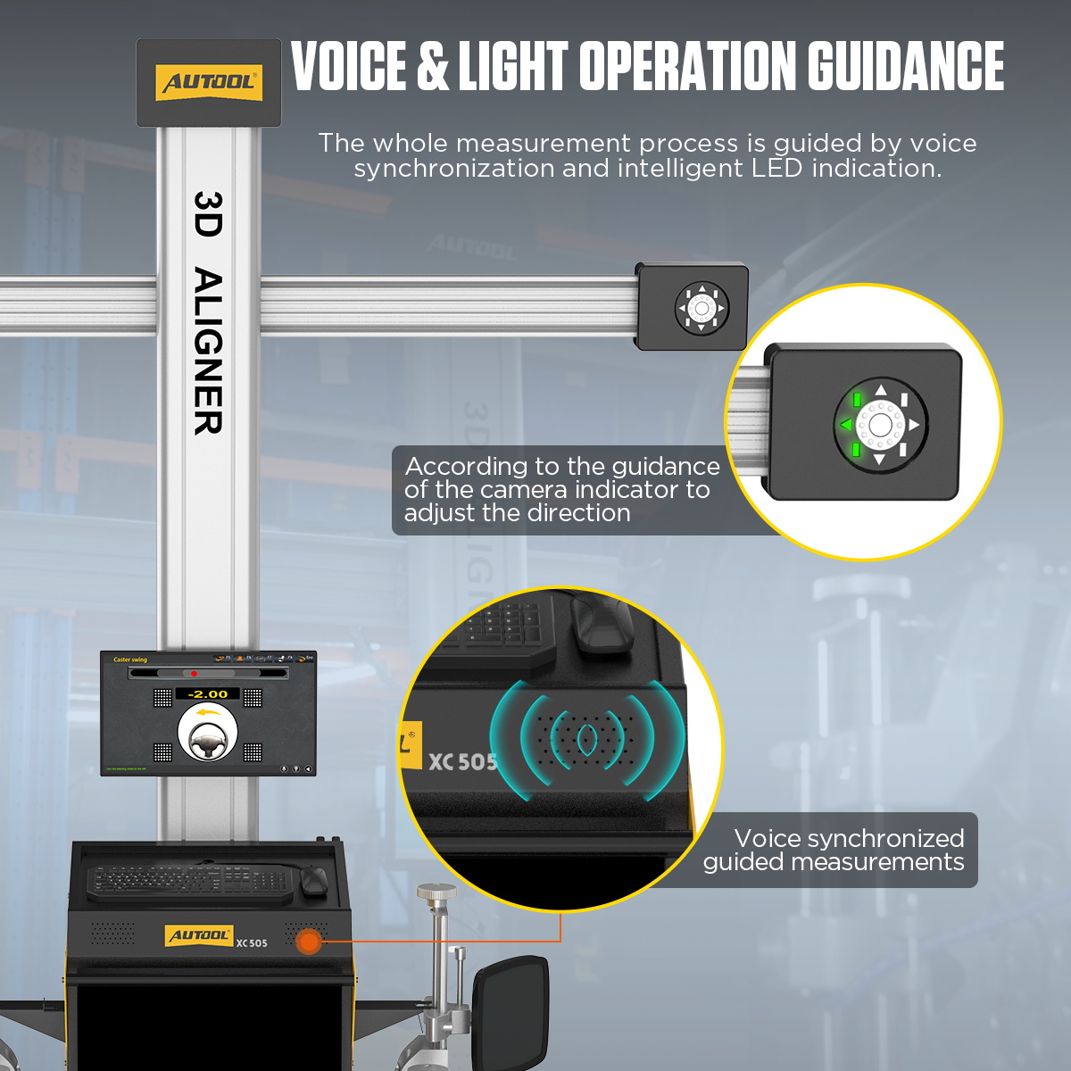
Confirm the lift is secure and level, the turntables and slip plates move correctly, the aligner uses a grounded stable supply, and direct sun or infrared reflection cannot strike the targets. Inspect cameras, filters, targets and clamps. The XC505 uses a cabinet-style mobile workstation with drawer storage; position it as instructed without disturbing the calibrated camera geometry. Do not move the column or open or adjust a camera to correct a setup problem.
Step 3: Position and secure the vehicle on the lift
Lock the turntables and side-slip plates, install the passing bridges and drive the vehicle squarely onto the alignment lift with the front wheels centered over the turntables. Center the steering wheel, chock as instructed, raise to the working height and place the transmission, parking brake and supports in the state required by the XC procedure.
Step 4: Mount each clamp and passive target
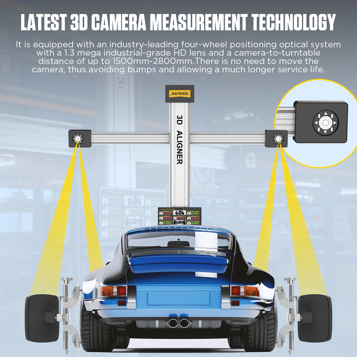
Match every target’s position label to the correct wheel, seat each clamp evenly and lock it without damaging the rim. Begin with targets near vertical, confirm all four are clean and fully visible to their cameras, and keep cables, people, lift posts and bodywork out of the optical path.
Step 5: Power on and select the exact vehicle record
Start the computer and enter Alignment Check. Search by manufacturer, model and year, then verify drivetrain, suspension and market variant against reliable OEM information before continuing. If the database record is absent or ambiguous, add or confirm specifications through the authorized data process instead of selecting the nearest-looking vehicle.
Step 6: Complete rolling run-out compensation
Install the passing bridges, center and lock the steering wheel, remove the brake pedal depressor for this stage, and follow the screen to push the vehicle backward and forward steadily. Keep targets close to vertical and continuously visible; the current product guidance describes a short 8-12 cm roll, but the live screen controls the exact movement. Remove the bridges when compensation finishes.
Step 7: Perform the caster and SAI steering sweep
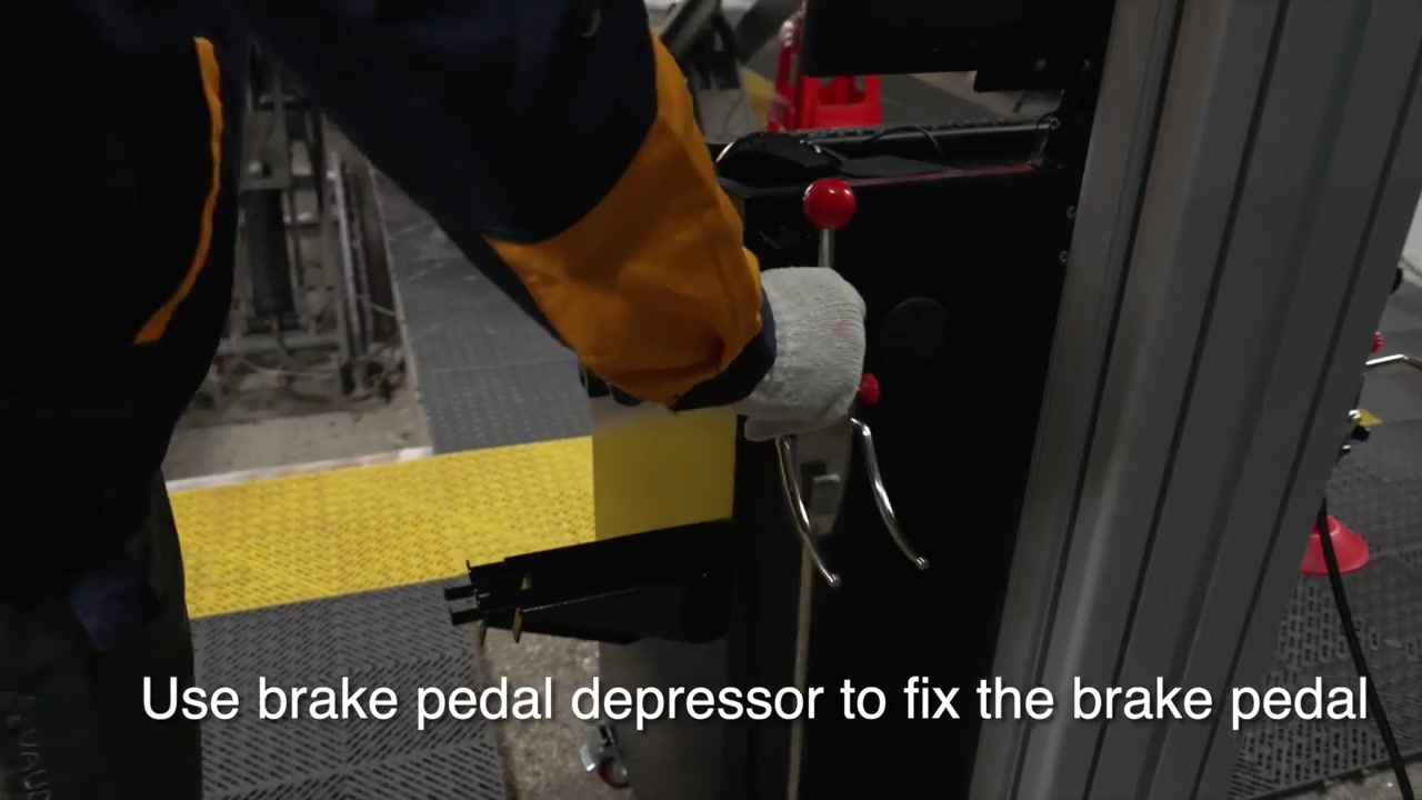
Before caster swing, install the brake pedal depressor and remove the steering-wheel holder. Follow the screen to center, turn right, turn left and return toward center until the indication completes. Never place hands or tools in a pinch zone while the wheels turn, and repeat the sweep if a target was blocked or the steering movement was not smooth.
Step 8: Interpret the measured angles against the right data
Review front and rear toe, camber, caster, SAI, thrust angle and any body dimensions required for the job. In the current XC software, green is within the selected OEM range, bright orange is outside it and white means no reference value is available. A color is only as reliable as the chosen vehicle record and completed compensation.
Step 9: Adjust the rear axle before the front when the vehicle allows
Follow the vehicle adjustment sequence and torque procedures. Where rear toe or camber is adjustable, establish the rear thrust line first, then center and adjust the front. Use the steering-wheel holder or brake depressor only at the stages that call for it, settle the suspension after changes and remeasure rather than chasing a live color alone.
Step 10: Repeat measurement and save the before-and-after report
After all fasteners are torqued and the suspension is settled, repeat the required compensation or measurement sequence. Confirm the steering wheel is centered and all final angles match the correct acceptance criteria. Save the vehicle record and use the connected workstation's available report output when a printed copy is needed.
Step 11: Remove equipment and restore the bay
Power down as instructed, remove the targets and clamps without dropping or scraping them, unlock plates only when the vehicle is secured, remove chocks and holders, and lower the lift. Clean target faces with neutral detergent or ethanol as permitted, keep camera filters clean and store every target where it cannot be knocked out of shape.
Step 12: Road-test and close the diagnosis
A qualified technician should road-test only when the vehicle is safe and local conditions allow. Confirm steering-wheel center, straight tracking and the original symptom, then recheck torque, tire condition or alignment if the result is not satisfactory. Preserve the before/after report with the exact vehicle and operator record.
Before removing any target, save the final measurement, confirm the steering wheel is centered, verify every adjustment is secure and preserve the before-and-after report for the road test.
Read and verify the result
Interpret the screen only after confirming the exact vehicle record, target visibility and completed compensation. Green means the value is inside the selected reference range, bright orange means it is outside that range, and white means the current database record has no reference value. A color is useful only when the setup and vehicle condition are valid.
- Use rear measurements and thrust direction to establish the vehicle centerline before final front toe and steering-wheel position, following the vehicle maker’s adjustment order.
- A white value is not a pass; it means there is no reference in the selected record and the correct service specification must be verified separately.
- If a target is blocked, loose or disturbed, restore the setup and repeat the required compensation instead of continuing from an unstable measurement.
- Save the initial and final values with the vehicle record. The before-and-after report is most useful when tire pressure, loading and adjustment conditions are also documented.
Stop if the lift moves unexpectedly, a turntable or slip plate is obstructed, a clamp or target shifts, a target leaves the camera field, readings remain unstable, the steering wheel cannot be held safely, or adjustment would exceed the vehicle procedure. Correct the mechanical or setup problem, then repeat compensation before trusting new values.
Common mistakes and care
- Only a trained wheel-alignment technician should operate the XC system or adjust steering and suspension components.
- Repair loose, worn or damaged tires, wheels, steering and suspension parts before using alignment readings for adjustment.
- Keep the lift level, targets visible and direct sunlight or infrared reflection away from the camera path.
- Do not move the column or open or adjust a camera; arrange authorized inspection or calibration if the optical geometry may have changed.
- Use the exact vehicle, year, market and suspension specification; a green result from the wrong database record is not valid evidence.
- Do not align around worn joints, incorrect tire pressure, a bent wheel or an unresolved ride-height problem.
- Do not select a nearby year or trim merely because it provides green values; confirm the exact vehicle record and any required loading condition.
- Do not move a camera structure, target or wheel clamp after compensation and then continue with the old compensation result.
- Do not treat the XC-series measurement capacity as the vehicle alignment specification.
- After the final measurement, remove clamps without marking the wheels, restore turntable and slip-plate locks as required, store clean targets securely and complete a controlled road test.
Frequently asked questions
Can the XC505 correct a pull when steering or suspension parts are worn?
No. Repair loose or worn parts, damaged tires, incorrect pressure and ride-height problems first. Alignment values measured on an unstable vehicle will not remain reliable.
What should I do if a target is blocked or the reading becomes unstable?
Stop the measurement, restore camera visibility and confirm the clamp and target have not moved. Repeat the required compensation before interpreting or adjusting from the new reading.
Does a green value guarantee the alignment is correct?
Only for the selected reference and current setup. Confirm the exact vehicle record, loading condition, mechanical condition and measurement procedure before treating green as acceptable.
Final XC505 checklist
- Vehicle identity, symptom, tire pressure and mechanical condition verified
- Lift level; turntables, slip plates and vehicle position prepared correctly
- Four clamps and targets secure, clean, oriented and visible
- Exact vehicle record selected; rolling compensation and caster sweep completed
- Adjustments made in the vehicle-specified order and final values remeasured
- Before-and-after report saved; equipment removed safely and road test completed
The XC505 produces a useful alignment result when the vehicle condition, lift geometry, target setup and database record are all controlled. Measure first, adjust in the specified order, remeasure after every relevant change and verify the finished vehicle on the road.


Comments 0
Questions, fixes, and real-world diagnostic notes from readers.
Be the first to share a diagnostic result or ask a follow-up question.