
How to Use the AUTOOL AST609 Brake Fluid Bleeder

The AUTOOL AST609 brake fluid bleeder draws new brake fluid from a removable external bottle and sends it through one filling hose to a sealed reservoir adapter. Prime that path away from the vehicle before connecting it to the reservoir.
The exact vehicle service procedure—not a pressure graphic, a mode name or a familiar wheel-order rule—must determine the fluid, permitted pressure, service-point sequence, electronic state, endpoint and final brake checks.
Before following any control step, verify that the AST609 in front of you has the current Standard/Fast selector and separate Start and Stop buttons. Those modes describe how the machine delivers fluid; they are not universal settings for a vehicle.
Choose a mode only if its operating condition remains within every applicable limit: the exact vehicle’s limit and the verified limits of the delivered AST609, reservoir and installed adapter. If that cannot be confirmed, do not pressurize the reservoir.
Brake and clutch hydraulics are safety-critical. This guide is for a trained operator who can obtain and follow current vehicle information, work safely around brake fluid, restrained vehicles, electricity and pressure, and keep an uncertain vehicle off the road. If the correct fluid, adapter, procedure or acceptance test is missing, the safe next step is to stop before opening the system.
In this guide
- AST609 workflow at a glance
- What the AST609 does—and what it cannot decide
- Before you start
- Know the current controls and fluid paths
- Phase A: qualify and identify
- Phase B: establish an air-free AST609 fluid path
- Phase C: seal the reservoir and service one point at a time
- If the normal cycle is interrupted
- Phase D: prove zero and release only a verified vehicle
- AST609 troubleshooting and stop rules
- Frequently asked questions
- Final AST609 checklist
- The job ends with a verified vehicle and a zero-pressure AST609
AST609 workflow at a glance
Use this dependency order:
- approve the exact vehicle procedure and initial hydraulic condition;
- identify the current-panel AST609 and its delivered instructions;
- verify the actual power lead, nameplate and electrical requirements;
- prepare the work area, exact new fluid, PPE, tools and waste controls;
- reconcile and inspect every delivered fluid, pressure and electrical part;
- fill and secure the removable new-fluid bottle;
- place the suction and pressure-balance hoses correctly and route the filling hose;
- prime the filling path away from the vehicle to steady bubble-free discharge;
- press Stop, wait at least 15 seconds and prove stable zero before reconfiguration;
- clean and inspect the reservoir opening;
- install the exact adapter and connect the primed filling hose;
- select an eligible mode and prove the whole pressure boundary dry and stable;
- prepare the first vehicle-prescribed service point and catch path;
- service and close one required point at a time under continuous observation;
- close the final active bleeder before pressing Stop;
- wait at least 15 seconds, prove stable zero and only then disconnect; and
- restore and verify the vehicle, control waste, care for the tool and record the result.
Do not skip ahead after a failed check. Close any open bleeder, press Stop, keep every pressure-side fitting assembled, wait and prove stable zero. Correct the cause, re-prime if air may have entered and return to the exact vehicle procedure before restarting.
What the AST609 does—and what it cannot decide
AST609 is a pressure-assisted filling and bleeding tool for an eligible vehicle brake or clutch hydraulic system. It takes clean fluid from an external bottle through a suction hose, uses a pressure-balance hose at that bottle and delivers primed fluid through one output to the reservoir adapter. Removed fluid is collected separately at one wheel, caliper, clutch or other prescribed hydraulic point.
The one-output design means that one service point is opened and observed at a time; AST609 is not a simultaneous multi-wheel system.
A one-person workflow is possible only when the qualified operator can continuously see the new-fluid reserve, bottle hoses, gauge, reservoir adapter, filling hose, active bleeder and used-fluid bottle. Add a second observer when a lift, vehicle body or hose route hides any part of that boundary.
Do not treat routine pressure bleeding as the default after a dry system, major component replacement, wrong-fluid contamination, falling reservoir level, hydraulic leak or unexplained pedal problem. Use the exact diagnostic or recovery procedure for that condition.
AST609 does not create a universal ABS, EPB, brake-by-wire, regenerative-braking, electronic-booster or scan-tool routine. Such work may require a specific ignition state, pump or valve activation, diagnostic command, repeated circuit, calibration or release test supplied by the vehicle manufacturer.
Treat Standard and Fast as labels on the delivered machine. Neither label is permission to exceed a reservoir limit or bypass a staged vehicle method. If the lowest usable AST609 condition is not permitted for the exact vehicle and adapter, choose a different approved method.
Before you start
Gather the exact vehicle decisions
Record these items before connecting power or opening the reservoir:
| Required decision | What you must know | Stop when |
|---|---|---|
| Vehicle eligibility | Pressure-assisted reservoir bleeding is permitted for this vehicle, hydraulic system and repair state | The current procedure is absent, incomplete or excludes this method |
| Brake fluid | Exact fluid specification plus handling and material restrictions | The fluid is unknown, mixed, previously opened without verified suitability, recovered or not confirmed compatible |
| Pressure method | Vehicle-prescribed method, maximum and any staged condition | You have only a tool capability, product image, forum number or another vehicle’s setting |
| Service sequence | Exact wheel, caliper, clutch or circuit order and every bleeder on each component | You have only a farthest-first, nearest-first or diagonal rule |
| Electronic state | Required ignition, engine, booster, ABS, EPB and diagnostic-tool state | Any activation, deactivation or calibration step is uncertain |
| Bleeder details | Correct tool, opening method, endpoint, closing method and final torque | A bleeder is seized, rounded, damaged or its requirements are unavailable |
| Reservoir adapter | Exact approved profile, attachment geometry and intact sealing element | It is only a near fit, must be forced or cannot sit squarely |
| Final acceptance | Fluid level and cap state, leak, pedal, warning, diagnostic and functional checks | Any required pass condition is unknown or cannot be completed |
Use the AUTOOL manual-download center to locate AST609, then compare those instructions with the document delivered with your machine and the physical panel in front of you. The delivered nameplate, input lead, controls and instructions must agree before use.
Prepare fluid, protection and access
Use enough new, unopened brake fluid of the exact vehicle specification for off-vehicle priming, the complete prescribed sequence and a visible safety reserve. Keep the original label available. Never mix fluid families, guess from color or pour used, priming, unknown or contaminated fluid into the new supply.
Wear eye protection and gloves compatible with the selected fluid. Keep its label and safety data sheet available. Protect vehicle paint, nearby plastics, electrical parts and the floor. Prepare compatible spill materials and labelled waste containers before fluid is opened.
Place the AST609 on a dry, clean, level, stable surface where the bottle and gauge remain visible. Restrain and support the vehicle by its approved method, control key access and keep bystanders outside the work area. Route hoses away from lift points, wheels, exhaust, sharp edges and walkways. Leave enough slack that vehicle position changes cannot pull on the reservoir adapter.
Prepare the exact bleeder tool, a snug clear hose, a stable compatible used-fluid bottle, clean lint-controlled materials and every diagnostic or service tool required by the vehicle procedure. Keep clean-side equipment physically separate from catch equipment.
Know the current controls and fluid paths
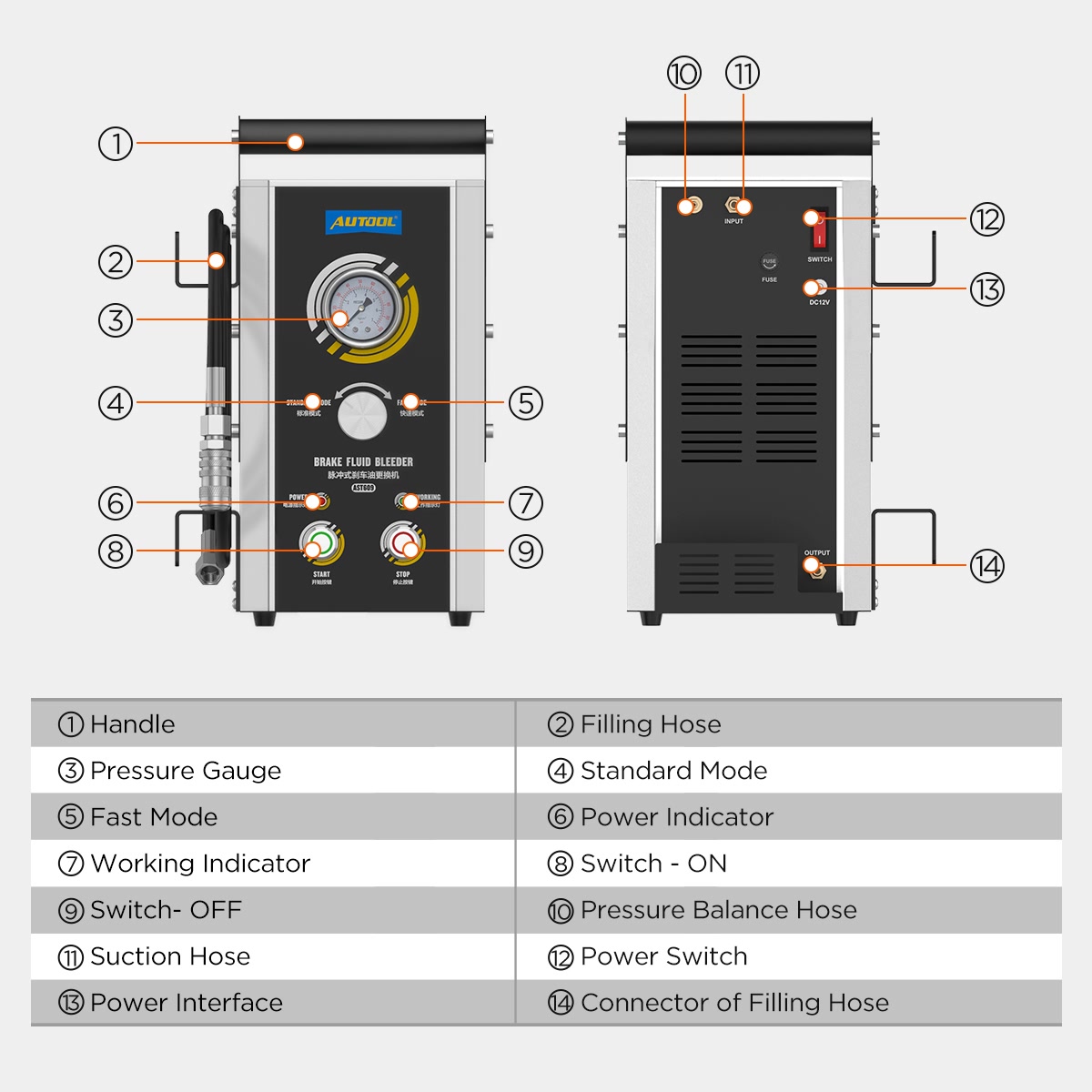
| Part or label | Its use in this procedure | What it does not authorize |
|---|---|---|
| Standard/Fast selector | Selects one of the delivered machine’s two labelled delivery modes after the vehicle pressure boundary is known | Treating either mode as a universal vehicle setting |
| Start button | Begins machine delivery after supply, priming, adapter, mode and pressure-boundary checks pass | One-button unattended service or repeated cycling to overcome a fault |
| Stop button | Stops active delivery before the required wait and stable-zero proof | Disconnecting immediately because the motor becomes quiet |
| Power and working indicators | Help confirm the panel state while following the delivered input instructions | Proving correct voltage, polarity, protective earth or zero pressure |
| Pressure gauge | Shows the machine-side condition and confirms return to zero | Proving pressure at every vehicle point or diagnosing the brake system by itself |
| Suction hose | Draws new fluid from the removable bottle | Running uncovered or being swapped by guess with the balance path |
| Pressure-balance hose | Maintains the bottle-side balance required by the delivered fluid path | Being omitted, blocked or used as the delivery output |
| Filling hose and output coupling | Carries primed fluid from AST609 to the reservoir adapter | Being reseated, tightened or released while pressure remains |
| Reservoir adapter and seal | Forms a temporary sealed boundary at the vehicle reservoir | Proving fit from a brand chart, adapter count or visual similarity |
| Clear bleeder hose and used-fluid bottle | Make removed fluid and bubbles observable at one active point | Deciding wheel order, fluid identity, pressure or the complete endpoint |
If your physical panel, connectors or labels do not match this control map, pause. Use the delivered instructions for that exact unit and obtain clarification before operating. A model name on an old image is not enough to transfer its buttons or sequence.
Phase A: qualify and identify
Step 1: Approve the vehicle procedure and initial hydraulic state
Read the complete current procedure for the exact vehicle, model year, installed brake equipment and repair state. Confirm that pressure-assisted reservoir bleeding is allowed. Record the fluid, method, maximum pressure, service-point order, required ignition or engine state, ABS or other electronic routines, bleeder operation and torque, endpoint, final checks and any controlled functional test.
Inspect the vehicle before disturbing the system. Look for an unexplained low level, wet hydraulic components, damaged lines or hoses, warning indicators and an abnormal pedal. Ask what work has just been performed and whether any circuit, master cylinder, ABS unit or other component may be dry.
A routine exchange is not the default response to wrong fluid, an unresolved leak, a dry system or an unexplained soft or sinking pedal. Those conditions need the exact diagnostic or recovery procedure. Do not expect pressure equipment to replace component repair, scan-tool activation or a complete air-recovery sequence.
Stop: Keep the reservoir closed and the vehicle stationary if eligibility, initial condition or any required vehicle-controlled instruction is uncertain.
Completion check: The exact current procedure permits the planned AST609 method, all vehicle-controlled decisions are recorded and the initial hydraulic condition is suitable for the defined job.
Step 2: Confirm the current-panel AST609 and its instructions
Find AST609 on the physical machine. Compare the panel with the current layout: a Standard/Fast selector, separate Start and Stop buttons, power and working indicators, and a pressure gauge. Trace the single filling output and the two bottle-side hoses so their roles are clear before anything is connected.
Do not identify the operating revision by housing color alone. Similar blue machines and older AST609 images can have different controls. Do not use an instruction that calls Fast by another label, and do not translate an older one-button action into the separate Start/Stop sequence.
Compare the delivered manual, panel, connectors, bottle, hoses and packing list. If a label is damaged or an instruction does not match the physical unit, keep the machine out of use until its correct operating information is confirmed.
Completion check: The physical machine is positively identified as AST609, its current Standard/Fast and separate Start/Stop controls match the instructions being followed, and every relevant connector is understood by function.
Step 3: Verify the delivered power path
Read the actual nameplate and inspect the input lead supplied with your unit. AST609 can appear with different power arrangements, so do not assume that every package contains both methods or that the machine changes input automatically.
If the delivered configuration uses an AC lead, match its nameplate, plug and outlet and verify a dry, intact protective-earth path. Do not use an adapter, extension arrangement or outlet that defeats grounding or introduces wet connections.
If the delivered configuration uses battery clamps, follow its exact connection order, required vehicle state and polarity markings. Keep clamps away from fluid, moving parts and accidental contact. Do not infer polarity or a safe battery procedure from a short demonstration.
With power disconnected, inspect the lead, plug or clamps, enclosure, strain relief, controls, gauge, bottle holder, hoses, couplings and visible fasteners. Remove the machine from service for cuts, exposed conductors, cracked insulation, loose parts, impact damage, fluid intrusion, corrosion, heat discoloration, an abnormal odor or a gauge that does not rest correctly.
Stop: Do not energize an unmatched, wet, damaged, ungrounded or polarity-uncertain configuration.
Completion check: The delivered nameplate, input lead, electrical supply, polarity or protective earth, controls and visible condition all match the exact instructions for this AST609.
Step 4: Prepare the work area, vehicle, fluid and tools
Protect painted panels around the reservoir and every service point. Establish safe access to each prescribed bleeder without placing yourself under an unsupported vehicle. Position the AST609 so an operator can see its gauge, bottle and reservoir hose while another person, if needed, watches the active service point.
Set out new, unopened, exact-specification fluid and enough reserve for priming and the complete vehicle procedure. Do not choose the job quantity from the removable bottle’s nominal size. Close spare fluid promptly and keep every clean cap, hose end and adapter protected from water, dust, lint and catch-fluid equipment.
Place compatible eye and hand protection, spill materials, clean wipes, the exact reservoir adapter, clear hose, restrained used-fluid bottle, bleeder tools, torque tool, labels and waste container within controlled reach. Confirm that all required diagnostic equipment is present, powered and updated before the hydraulic sequence begins.
Arrange communication between operators. Agree on commands such as open, close, Stop and zero confirmed so nobody changes a hydraulic or pressure connection based on assumption.
Completion check: The vehicle is safely supported, the risk boundary is observable, the exact fluid and adapter are confirmed, and every person, tool, clean item and waste container has a controlled position.
Step 5: Reconcile the delivered items and inspect the complete system
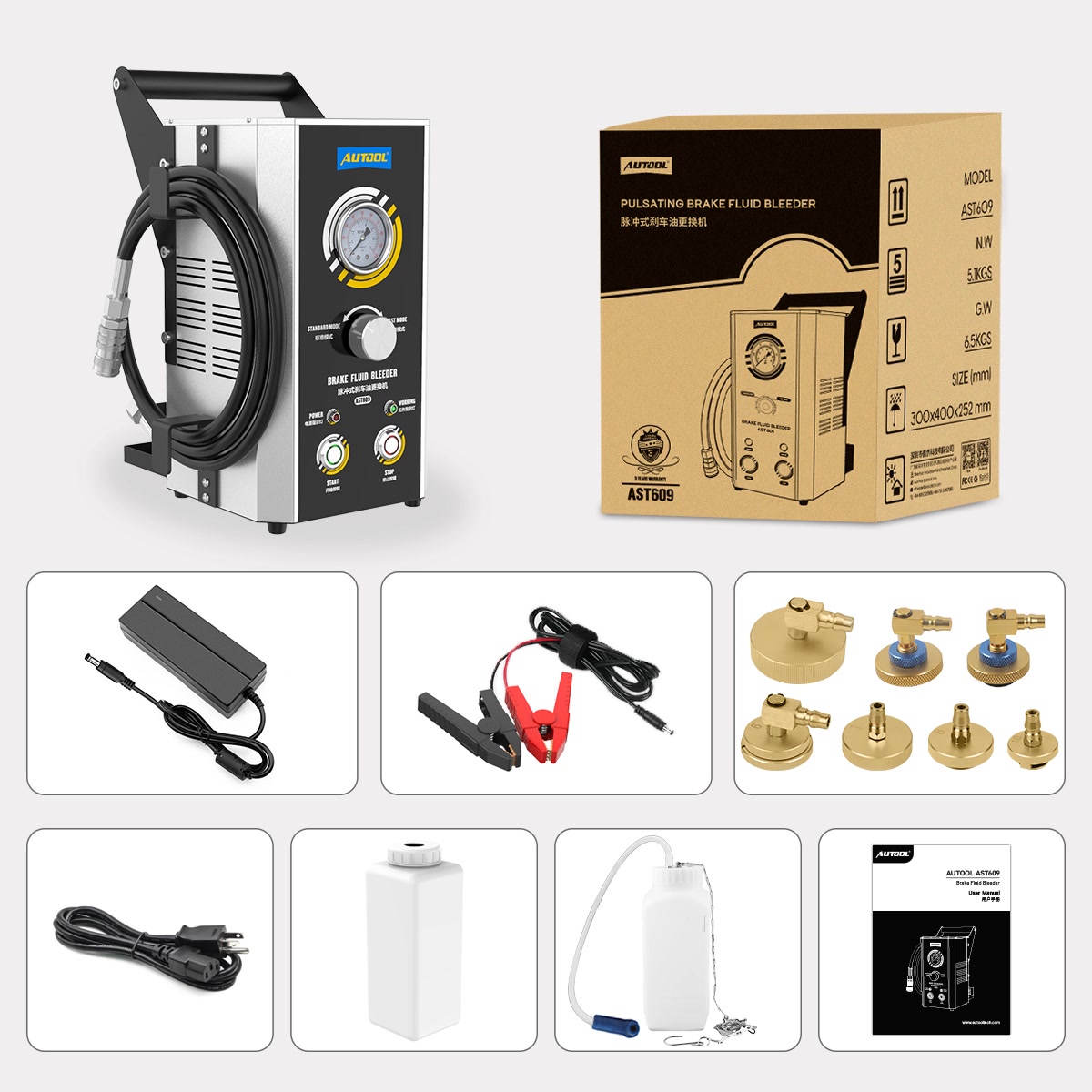
Lay out the machine, external bottle, suction hose, pressure-balance hose, filling hose and output coupling, reservoir adapters, clear capture hose and used-fluid bottle. Check them against the packing list that came with your order. Do not assume that an expanded adapter case or every item seen in a product composition is part of the base package.
Inspect the external bottle for cleanliness, chemical compatibility, cracks and stable seating. Inspect each hose along its full length for cuts, hardening, swelling, abrasion, kinks, contamination, loose fittings or unapproved repairs. Check the output coupling for complete movement and a clean protected interior.
Inspect each candidate adapter’s body, profile, threads or locking features and sealing element. Reject a split, flattened, swollen, hardened, missing or contaminated seal. Inspect the clear catch hose and used-fluid bottle independently; a storage position on the machine does not prove that the bottle will remain stable during use.
Check that the gauge rests normally with the machine off and depressurized. Do not operate with a stuck, damaged or doubtful gauge because it is the required indicator for the stable-zero gate.
Completion check: Every required electrical, clean-fluid, pressure and collection component is present, clean, intact, correctly identified and reconciled with the actual order.
Phase B: establish an air-free AST609 fluid path
Step 6: Fill and secure the external new-fluid bottle
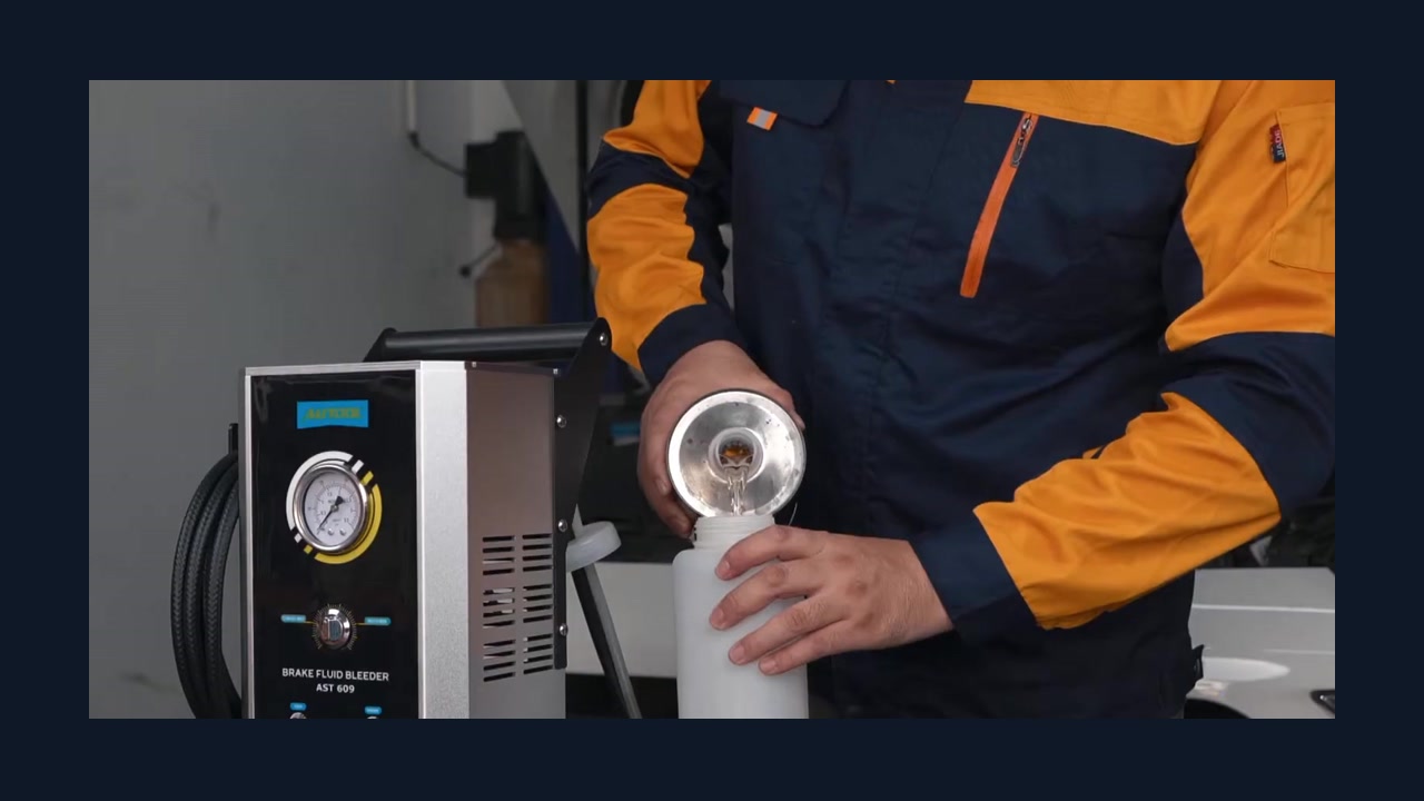
Keep the machine de-energized. Verify the fluid label against the vehicle procedure one more time. Fill the clean external bottle with enough new fluid for the planned prime and service plus a visible reserve, without treating bottle capacity as the job quantity.
Seat the bottle in its holder or approved support so it cannot tip, slide or be pulled by a hose. Keep its outside dry and prevent fluid from reaching the machine’s electrical parts. Minimize unnecessary exposure of the selected fluid to air and contamination according to its handling instructions.
Keep the suction hose and pressure-balance hose ends clean while the bottle is filled and positioned. Do not let either end touch the floor, used-fluid equipment or an unclean surface before placement.
Do not add recovered fluid, priming discharge or fluid from an unlabelled container. If the wrong fluid enters the bottle or clean-side hose, do not connect the vehicle; isolate the equipment and follow the correct contamination procedure.
Do not rely on low-fluid protection as the operating level control. Its trigger and recovery behavior do not replace continuous observation of the reserve.
Completion check: The external bottle contains enough of the correct new fluid, sits upright and secure, remains dry outside and can be continuously observed throughout the job.
Step 7: Place the suction and pressure-balance hoses and route the filling hose
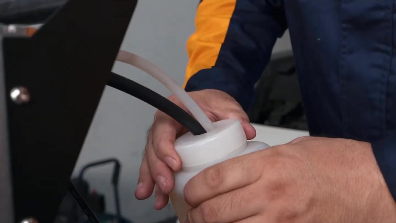
Identify the suction hose and pressure-balance hose from their actual machine connections and delivered instructions. Put both ends into their specified positions at the bottom of the external new-fluid bottle. Keep the hoses separated enough to observe them, but do not bend, clamp, block or swap them.
Arrange the ends so vehicle or machine movement cannot pull either one out. Both must remain covered by clean fluid through priming and the complete service. If the reserve might fall below either hose, add the exact new fluid only through a safe depressurized process before continuing.
Route the filling hose from the AST609 output toward the priming collector and later reservoir position. Keep the coupling clean, leave generous slack and prevent kinks, abrasion, heat, sharp-edge contact and trip hazards. Do not let the hose support the machine or pull on the adapter.
Make a visibility check from the operator positions. If nobody can see the bottle, gauge, reservoir connection and active bleeder at the same time, assign a second observer before pressure begins.
Completion check: The suction and pressure-balance hoses are correctly placed, covered and unkinked; the filling hose is clean, protected and slack; and the whole operating boundary can be observed.
Step 8: Prime the filling path away from the vehicle
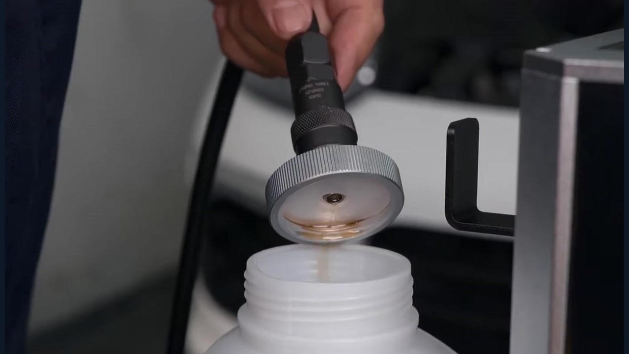
Connect the priming adapter or outlet arrangement specified for the delivered AST609 to the filling-hose coupling, but do not install it on the vehicle. Point and hold the outlet inside a stable compatible collector so discharge cannot spray toward eyes, paint, electrics or the floor.
Connect the verified power path by its exact instructions. Use the delivered instructions to select the required priming mode; do not choose Fast simply to shorten the step. Press Start only after the supply, suction hose, pressure-balance hose, filling hose, collector and operators are ready.
Watch the external reserve, both bottle hoses, every coupling, the outlet and the gauge while fluid fills the path. Continue until the discharge is steady and remains free of bubbles. Elapsed time alone cannot prove that all air has left the clean-side path.
Stop: Press Stop for no flow, an uncovered or moving bottle hose, leakage, unstable pressure, a detached line, abnormal sound, heat, odor, smoke, electrical tripping or fluid near live parts. Keep the outlet controlled while the system depressurizes.
Completion check: The priming outlet produces a steady bubble-free flow, both bottle-side hose ends remain covered by clean fluid and every visible machine-side connection stays dry, secure and stable.
Step 9: Press Stop, wait and prove stable zero before reconfiguration
Press Stop while the priming outlet remains controlled. Do not remove the outlet or coupling. Wait at least 15 seconds, continue watching the gauge and confirm that its indication reaches zero and remains there.
Motor silence, an extinguished working light or a gauge that merely passes through zero is not enough. Stable zero means the pressure indication settles at zero while the filling hose, coupling and outlet remain assembled and show no pressure effect.
After stable zero is confirmed, follow the delivered AST609 instructions for the power state required during reconfiguration. Control drips and remove only the priming connection needed for the next step. Protect the primed filling-hose coupling from dirt and do not drain the clean path unnecessarily.
If the gauge will not reach or hold zero, keep the pressure boundary intact. Do not crack a fitting or pull the coupling to vent it. Follow the delivered unloading procedure; if it is unavailable or unsuccessful, isolate the machine and obtain qualified service.
Completion check: Stop has been pressed, at least 15 seconds have passed, the gauge remains stably at zero and the primed filling hose stays clean without any live pressure-side fitting being moved.
Phase C: seal the reservoir and service one point at a time
Step 10: Protect and prepare the reservoir
Protect nearby painted surfaces and arrange compatible spill control before touching the cap. Clean loose dirt from around the reservoir opening without allowing water, solvent, lint or debris inside. Inspect the reservoir, cap, diaphragm, neck, threads or locking features and sealing surface for damage.
Reconfirm the exact fluid specification, permitted pressure-assisted method and vehicle state. Check whether the vehicle procedure requires a particular starting level, screen removal, diaphragm position, ignition state or diagnostic preparation. Do not generalize those details from another reservoir.
Open the reservoir only after the area is clean. Prevent tools, adapter parts and hoses from touching contaminated surfaces. If the existing fluid is unknown, visibly contaminated or inconsistent with the required specification, stop and use the vehicle manufacturer’s contamination procedure rather than pushing new fluid through an uncertain system.
Completion check: The reservoir area and sealing surface are clean and undamaged, the fluid and method are reconfirmed, and every vehicle-specific preparation is complete without introducing contamination.
Step 11: Install the exact adapter and connect the primed output
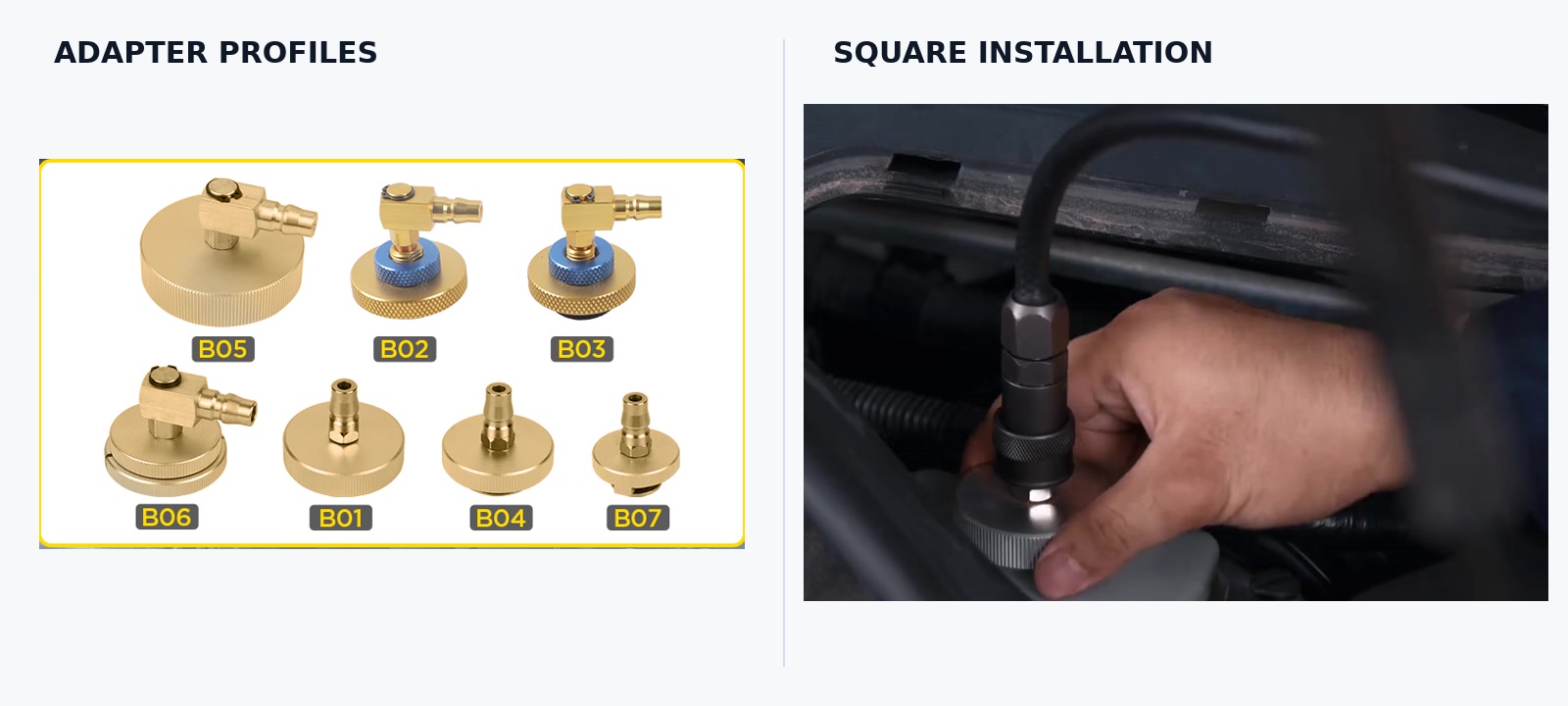
Compare the reservoir opening with the adapter profile, thread or locking geometry and sealing element specified for that exact reservoir. Select the exact clean, intact adapter. Do not choose by make alone; reservoirs can differ within one brand or model family.
Fit the adapter squarely using its intended attachment method. Never force, cross-thread, shim or improvise a near fit. Do not use machine pressure to pull an adapter into place. The body and seal must remain evenly seated and stationary during a light hand check.
With AST609 stopped and stably at zero, connect the primed filling-hose coupling fully to the adapter. Route the hose so it cannot twist the adapter, contact a hot or moving part or become tensioned when the vehicle is raised or lowered.
Keep every bleeder closed while the temporary reservoir boundary is assembled. Protect the area below the adapter so a small connection drip cannot reach paint or electrical parts.
Completion check: The exact adapter sits squarely with an intact seal, the primed output coupling is fully seated, the hose is untensioned and all vehicle service points remain closed.
Step 12: Select an eligible mode and prove a dry stable boundary
Review the exact vehicle pressure method and maximum before touching the selector. Confirm which delivered AST609 mode, if either, can remain within that boundary. Standard and Fast are machine labels; Fast is not automatically better, and neither label overrides the reservoir, adapter or vehicle limit.
Set the vehicle’s required ignition, engine, booster and diagnostic state exactly as instructed. Connect or enable the delivered power path. Select the eligible mode and press Start while watching the gauge, bottle reserve, suction hose, pressure-balance hose, filling hose, coupling, adapter, reservoir and all nearby surfaces.
Allow the machine-side condition to establish only within the approved vehicle and equipment boundary. Do not chase a product image, copied number or particular needle movement. Some gauge motion may occur during pulsing, but no generic amount of movement proves normal operation. Stop for unexplained surge, collapse, drift, hose expansion, adapter movement, seepage or abnormal sound.
Hold the closed system only long enough to prove that every visible boundary remains dry, secure and stable at the permitted condition. If a mode cannot meet the vehicle requirement without exceeding a limit, stop and use a different approved method.
Stop: If the adapter, reservoir, hose or coupling moves, swells or leaks, press Stop, wait at least 15 seconds and prove stable zero before touching it. Replace or correct the exact defective part while depressurized.
Completion check: An eligible delivered mode maintains the vehicle-approved condition while the external supply and complete machine-to-reservoir boundary remain visible, stationary, dry and stable.
Step 13: Prepare the first prescribed service point and catch path
Go to the first point named by the exact vehicle procedure. Do not substitute a generic farthest-wheel-first, nearest-wheel-first or diagonal order. Some vehicles have unusual hydraulic routing, electronic activation requirements or multiple bleeders on one component.
Clean around the exact bleeder without pushing debris inward. Inspect it for corrosion, rounding, cracks or previous damage and use the correct-size tool. Do not force a seized bleeder; resolve it through the applicable repair procedure before continuing.
Fit a snug clear hose to the bleeder and route it into a stable, compatible and labelled used-fluid bottle. Restrain the bottle so the hose cannot pull it over. Keep the hose clear of heat, sharp edges, moving parts and lift components, and keep the bottle arranged as designed rather than sealing an unapproved pressure vessel.
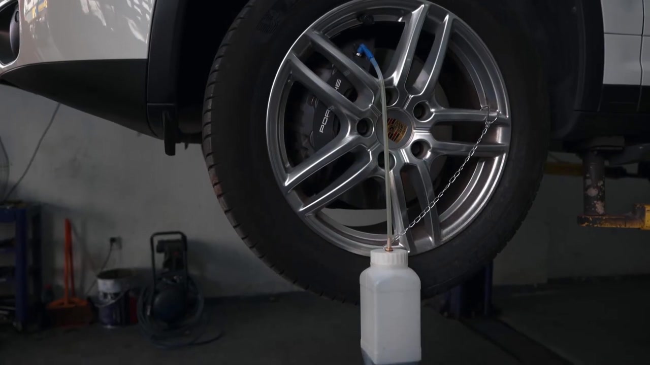
Confirm sight lines and communication. One operator must see the active bleeder and capture flow. That operator or a second observer must also see the new-fluid reserve, bottle hoses, gauge, reservoir adapter and filling hose.
Completion check: The exact first service point is clean and serviceable, the correct tool fits, the clear hose and catch bottle are secure, and the entire supply-to-capture boundary remains observable.
Step 14: Service, close and inspect each required point
Open only the active bleeder by the amount and method specified for that component. Observe fluid through the clear hose while maintaining the vehicle-prescribed machine condition. Do not open a second point at the same time.
Continuously monitor the external reserve, suction hose, pressure-balance hose, gauge, filling hose, coupling, reservoir adapter, active bleeder, clear hose and used-fluid bottle. Someone must be able to press Stop immediately or direct the machine-side operator to do so. One-person operation never means leaving the machine or fluid path unattended.
Meet the full vehicle-prescribed endpoint. Steady bubble-free flow can be one required observation, but it does not by itself prove correct fluid chemistry, quantity, circuit completion or safe pedal behavior.
Fluid color alone cannot define the endpoint. Apparent bubbles can also enter around bleeder threads or a loose clear-hose connection. Inspect the external catch path before deciding that every visible bubble came from inside the brake system.
When the exact endpoint is met, close the active bleeder by the prescribed method while machine pressure remains controlled. Apply only the specified final torque, restore its cap if required and inspect for seepage. Confirm closure before moving the hose and bottle to the next prescribed point.
Repeat the same controlled sequence for each required point. If a scan-tool activation or repeated circuit is required, follow it exactly and keep the normal AST609 pressure and supply controls in place. Do not invent an activation or substitute pedal pumping for diagnosis.
Stop: Close the active bleeder and press Stop for low supply, either bottle hose uncovering, air entry, no flow, persistent unexplained bubbles, a detached clear hose, pressure collapse or drift, adapter leakage, any external fluid leak, a damaged bleeder or electrical abnormality. Wait and prove stable zero before correction.
Completion check: Every completed point reached its exact endpoint, was closed and remained externally dry before the next point began, with no loss of clean-fluid reserve, boundary control or catch-path control.
If the normal cycle is interrupted
| What you observe | Immediate safe action | Before restarting |
|---|---|---|
| New-fluid reserve becomes low or either bottle hose uncovers | Close the active bleeder, press Stop, wait and prove stable zero | Restore the correct clean supply, re-prime off the vehicle and follow the exact air-recovery or complete re-bleed procedure |
| Bubbles do not clear | Close the active bleeder and Stop without declaring the point complete | Inspect the clear-hose and bleeder interface and use the vehicle’s diagnostic or repeat path |
| No fluid flows | Close the bleeder, Stop and keep every fitting assembled until stable zero | Check the prescribed bleeder, vehicle valve or diagnostic state, external supply, adapter boundary and machine setup; do not change pressure by guess |
| Pressure does not build or remain stable | Close any open bleeder and press Stop | After the wait and stable-zero proof, inspect only visible external supply and boundary points; obtain service for a machine or gauge fault |
| Adapter, reservoir or filling hose moves, swells or leaks | Close the bleeder if open, press Stop and keep clear while pressure decays | Replace the exact damaged or mismatched component only after stable zero; never tighten or hold it live |
| A hose detaches or air enters the clean or vehicle path | Close the active bleeder, press Stop and prove stable zero; mark the normal cycle incomplete | Re-prime and complete the exact vehicle air-recovery, ABS or full re-bleed sequence before release |
| Gauge does not reach or remain at zero | Leave the complete pressure boundary assembled | Follow the delivered unloading and service instruction; never pull a coupling or loosen a fitting to vent |
| Fluid contacts a person, paint, electrical parts or the floor | Close the active bleeder, press Stop, wait, prove stable zero and isolate when safe; control the exposure or spill | Follow the fluid label, SDS and vehicle-finish procedure before work resumes |
An interruption can invalidate more than the point currently open. The exact vehicle procedure determines whether you repeat one point, one circuit, all service points or a diagnostic activation. A clear-looking hose does not cancel a known air-entry event.
Step 15: Close the final active bleeder before pressing Stop
At the final required service point, maintain the correct clean-fluid reserve and the approved pressure boundary until the complete vehicle endpoint has been met. Close the bleeder by the exact method and apply its final torque as required.
Inspect the bleeder and catch-hose connection. Confirm that the bleeder is fully closed and externally dry before pressing Stop. Only then should active delivery end.
This order prevents the open service point from becoming an air-entry path as pressure falls. Do not reverse it because the discharge looks clean, bubbles are no longer visible or a presumed quantity has passed.
Completion check: The final vehicle-prescribed endpoint is met and the final bleeder is closed, tightened and externally dry while the reservoir pressure boundary remains controlled.
Phase D: prove zero and release only a verified vehicle
Step 16: Press Stop, wait, prove stable zero and disconnect
After the final active bleeder is closed, press Stop. Keep the filling hose, output coupling and reservoir adapter assembled. Wait at least 15 seconds while watching the gauge and the physical pressure boundary.
Confirm that the gauge reaches zero and remains there. A stopped pump, inactive indicator or brief zero reading is not the gate. Open the connection only after stable zero is proved and no hose, coupling or adapter shows a visible sign of residual pressure.
Then follow the delivered AST609 instructions for switching off and isolating its power supply. Different input arrangements can require different disconnection sequences. Do not assume an AC and battery-clamp path use the same order.
If stable zero cannot be proved, keep the boundary intact. Do not turn an uncertain control by guess, loosen a pressure-side fitting, pull a coupling or remove the adapter. Isolate the work area and obtain qualified support under the delivered machine procedure.
Once the gauge remains at zero, protect the reservoir and paint from drips. Release the filling-hose coupling by its intended mechanism, then remove the reservoir adapter squarely without introducing dirt.
Completion check: Stop has been pressed, at least 15 seconds have elapsed, the gauge remains stably at zero, the delivered power instruction is complete and the reservoir boundary is removed without spray, force or contamination.
Step 17: Restore and verify the vehicle, then close out the equipment
Set the reservoir to the exact vehicle-specified final level using only the correct clean fluid. Inspect and install the diaphragm, cap, seal and any screen by the vehicle procedure. Control exterior drips with methods compatible with the fluid and vehicle finish.
Inspect the reservoir area, every disturbed hydraulic point and each serviced bleeder for leakage. Complete the required stationary pedal application and hold check in the specified ignition, engine and booster state. Complete all required brake warning, ABS, EPB, scan-tool, fault, basic-setting and calibration checks. Recheck fluid level whenever the procedure requires it.
Do not move the vehicle with leakage, a falling level, a soft, sinking or inconsistent pedal, a brake warning, an unresolved fault, an incomplete electronic step or uncertainty about air entry. A qualified operator may perform a controlled functional or road test only after every stationary gate passes and only as prescribed for the exact vehicle.
Treat priming discharge and removed fluid as used material. Seal and label it in compatible containers, keep it away from the clean supply and use the lawful local disposal route. Never return it to the vehicle or external bottle.
With AST609 at stable zero and safely de-energized, perform only the external care allowed by its delivered instructions. Control drips and inspect the bottle, holder, hoses, coupling, adapters, catch equipment, lead and enclosure. Keep liquid away from electrical parts. Do not invent an internal flushing chemical, open the enclosure, substitute a protective part or adjust the pump, gauge or controls.
Follow the delivered storage instruction for residual fluid and preservation. If it does not clearly cover your fluid or storage period, isolate the machine and ask qualified support rather than improvising. Store it dry, protected from impact, heat, humidity, lead strain and hose damage.
Record the vehicle identity and repair state, exact fluid and container lot, AST609 identity, delivered power path, adapter, prescribed mode, vehicle boundary, actual point sequence and endpoints. Include every interruption, bubble or leak observation, recovery step, final level, cap, pedal, warning and diagnostic result, waste route, tool condition and vehicle release decision.
Completion check: The reservoir and every serviced point are sealed and dry, all vehicle acceptance tests pass, the vehicle release decision is recorded, used fluid is segregated and the zero-pressure AST609 is externally clean and safely stored.
AST609 troubleshooting and stop rules
Use these checks only after any active bleeder is closed, Stop has been pressed, at least 15 seconds have elapsed, stable zero is proved and the delivered power path is isolated.
| What you observe | Safe post-isolation check | Do not do |
|---|---|---|
| No power or abnormal startup | Recheck the delivered nameplate, input lead, correct supply, polarity or protective earth and visible lead condition | Try another voltage, reverse clamps by guess, bypass earth, substitute a protective part or open the enclosure |
| No bubble-free output during priming | Recheck the correct new fluid, covered suction and balance hoses, their identities, routing, coupling and visible external leaks | Connect an unprimed output to the vehicle or continue with an uncertain supply |
| Adapter does not sit squarely | Recheck the exact reservoir application, profile and sealing element | Force, cross-thread, shim or improvise a near-fit seal |
| Neither mode is compatible with the vehicle limit | Recheck the exact procedure and delivered machine boundary | Select Fast for convenience or exceed the vehicle limit; use a different approved method |
| Pressure does not build | Recheck reserve, hose placement, selected eligible mode, output coupling, adapter and visible leaks | Repeatedly press Start or change mode to overpower a fault |
| Pressure drifts, collapses or surges unexpectedly | Close the active bleeder, press Stop, wait, prove stable zero and inspect the visible boundary | Treat any pulsation as automatically safe or tighten a live fitting |
| Supply falls unexpectedly | Close the active bleeder, press Stop and return to stable zero | Depend on low-fluid protection or continue until a hose uncovers |
| Persistent bubbles at one service point | Inspect the clear-hose and bleeder interface, then follow the exact repeat or diagnostic procedure | Use color alone or assume every bubble comes from inside the circuit |
| Fluid leaks outside the catch path | Close the active bleeder, press Stop, wait, prove stable zero, isolate and control the spill | Wipe, hold, tighten or reseat the leaking part while pressurized |
| Gauge does not return to zero | Keep the assembly intact and follow the exact delivered unloading or service path | Crack a fitting, pull the adapter or open the enclosure to release pressure |
| Pedal remains soft, sinks or changes | Keep the vehicle stationary and perform the exact diagnosis and re-bleed process | Pump generically or road-test to see whether it improves |
| Warning or diagnostic step remains incomplete | Finish the exact vehicle routine or obtain qualified support | Clear or ignore a fault without resolving its cause and passing verification |
Keep a damaged or doubtful AST609 out of use even if it can still move fluid. Internal electrical, pump, gauge, control, calibration and pressure-system work belongs to qualified service.
Frequently asked questions
Which AST609 mode should I use?
Use only a delivered Standard or Fast mode that keeps the complete machine, adapter and reservoir condition within the exact vehicle’s prescribed method and maximum. A mode name is not a recommendation. If neither mode is compatible, do not use AST609 for that procedure.
What pressure should I use?
Use the exact current vehicle pressure and method, provided it is also within the verified limits of the delivered AST609, adapter and reservoir. Do not copy a product image, gauge photo, generic article or another vehicle’s number.
Which brake fluid can go in the bottle?
Use only new, unopened fluid of the exact vehicle specification and confirmed compatible with the delivered equipment. Do not mix families or return priming or removed fluid to the bottle.
Does AST609 have an internal clean-fluid tank?
The workflow shown here uses the removable external new-fluid bottle. The suction and pressure-balance hoses go to that bottle, while the filling hose runs from the single machine output to the reservoir adapter. Do not pour fluid into an assumed internal tank.
What is the pressure-balance hose for?
It maintains the required bottle-side balance in the delivered AST609 fluid path. Identify it from the actual connections and instructions, place it correctly near the bottom with the suction hose and never omit, block or swap it by guess.
Can I use either AC power or battery clamps?
Use only the input arrangement actually supplied and identified for your unit. Match the nameplate, lead and instructions. Do not assume both leads are included or that AST609 switches between inputs automatically.
Which wheel should I bleed first?
Use the exact current vehicle sequence. Do not default to farthest-first or another familiar rule. Hydraulic routing, electronic systems and multi-bleeder components can require a different order.
Are all adapter cases included?
Package contents can vary. Reconcile your order against its packing list and then prove adapter fit from the exact reservoir geometry and intact seal. A pictured case, adapter count or brand association is not fit proof.
Can one person operate AST609?
Only when one qualified person can continuously see the bottle reserve, both bottle hoses, gauge, adapter, filling hose and active service point. Use a second observer whenever any risk point is hidden. One-person operation never means unattended operation.
Can AST609 bleed ABS, EPB or brake-by-wire systems?
Only when the complete exact vehicle procedure expressly allows pressure-assisted bleeding and supplies every required ignition, pump, valve, diagnostic, sequence and final-verification step. AST609 does not create a universal electronic brake routine.
What if bubbles never stop?
Close the active bleeder, press Stop, wait and prove stable zero. Check the clear-hose and bleeder interface, clean supply path and reservoir boundary, then follow the exact vehicle diagnosis or repeat procedure. Do not simply choose Fast or keep consuming fluid.
Is clean-looking fluid enough to finish?
No. Color is only one observation. Meet the complete vehicle-prescribed quantity, cycle, diagnostic routine or other endpoint and any required bubble-free observation, then pass the final level, cap, leak, pedal, warning and diagnostic checks.
What if the gauge will not stay at zero?
Keep the filling hose, coupling and reservoir adapter assembled. Follow only the delivered unloading or service instruction. If zero cannot be maintained, isolate the machine and obtain qualified support. Never loosen a pressure-side fitting to vent it.
Can I reuse fluid collected during priming?
No. Priming discharge and removed fluid can contain air, moisture or contamination. Keep them out of the clean bottle and vehicle, then seal, label and dispose of them through the correct local route.
Can fluid remain in AST609 during storage?
Follow the exact storage and preservation instruction delivered with your unit and the selected fluid’s handling limits. If the instruction does not clearly answer your condition, isolate the tool and ask qualified support instead of improvising an internal flush.
What if the brake pedal is still soft after the job?
Keep the vehicle stationary. A soft, sinking or inconsistent pedal can indicate remaining air, leakage, an incomplete electronic routine or another hydraulic or mechanical fault. Complete the exact diagnosis and recovery procedure; do not use a road test to find out whether uncertain brakes improve.
Final AST609 checklist
Before power:
- the exact vehicle procedure permits pressure bleeding and defines fluid, pressure, order, electronic state, endpoints and release tests;
- the machine is the current-panel AST609 with Standard/Fast selection and separate Start/Stop controls;
- the delivered nameplate, input lead, polarity or protective earth and supply all agree;
- the work area, vehicle support, exact new fluid, adapter, PPE, tools and waste controls are ready; and
- every hose, coupling, seal, gauge, lead and container is clean, intact and correctly identified.
Before vehicle pressure:
- the external new-fluid bottle is stable with sufficient visible reserve;
- the suction and pressure-balance hoses are correctly placed near the bottom and remain covered;
- the filling hose is clean, protected and untensioned;
- the output path was primed off the vehicle to steady bubble-free discharge; and
- Stop was pressed, at least 15 seconds passed and stable zero was proved before the change from priming to vehicle connection.
At every service point:
- the exact reservoir adapter and output coupling remain square, dry and stable;
- the selected mode stays within the vehicle-prescribed boundary;
- supply reserve, both bottle hoses, gauge, adapter, filling hose and active catch path remain visible;
- only the exact prescribed point is open; and
- its full endpoint is met and the bleeder is closed and checked before moving on.
Before disconnection and release:
- the final active bleeder closed before Stop was pressed;
- at least 15 seconds passed and the gauge remained stably at zero before any pressure fitting moved;
- final reservoir level and cap state, every disturbed point, pedal behavior, warnings and required diagnostics pass;
- no leak, falling level, soft, sinking or inconsistent pedal, unresolved fault or uncertainty remains; and
- used fluid, tool condition, recovery events and the release decision are recorded.
The job ends with a verified vehicle and a zero-pressure AST609
A correct AST609 workflow is defined by control of air, pressure and sequence rather than by speed. It begins with the exact vehicle procedure, correct unopened fluid, a verified current panel and the delivered power path. It uses the external bottle, keeps both supply hoses covered, primes away from the vehicle and proves the reservoir adapter dry and stable before a service point opens.
The job is complete only when every prescribed point has reached its exact endpoint and been closed before machine output stops. At least 15 seconds must pass, and AST609 must remain at stable zero before disconnection. The restored vehicle must then pass every level, cap, leak, pedal, warning and diagnostic check. If any condition is unresolved, keep the vehicle stationary and keep the job open.


Comments 0
Questions, fixes, and real-world diagnostic notes from readers.
Be the first to share a diagnostic result or ask a follow-up question.