
How to Use the FXTUL F803 Smoke Leak Detector

The FXTUL F803 combines a built-in air source, pressure gauge, flow meter, flow-control valve and visible smoke. Use those features as one controlled sequence: define the low-pressure test boundary, establish the permitted air-only state, read pressure and flow together, then turn on smoke to locate the first unintended exit. After repair, repeat the same setup instead of comparing two different tests.
The displays do not supply a universal pass number. Pressure and flow depend on the vehicle system, designed vents, valve state, adapter seal, test volume and the position of the F803 flow-control valve. The exact vehicle procedure must define the entry point, isolation state and allowable pressure before you interpret either instrument.
Updated August 28, 2026.
In this guide
- Make sure this is the correct F-series guide
- Check the kit and prepare the work area
- Know what each F803 control tells you
- FXTUL F803 step-by-step pressure, flow and smoke test
- What the F803 does not decide for you
- Troubleshoot without forcing a result
- Store and maintain the F803
- Frequently asked questions
- What a complete F803 job looks like
Make sure this is the correct F-series guide
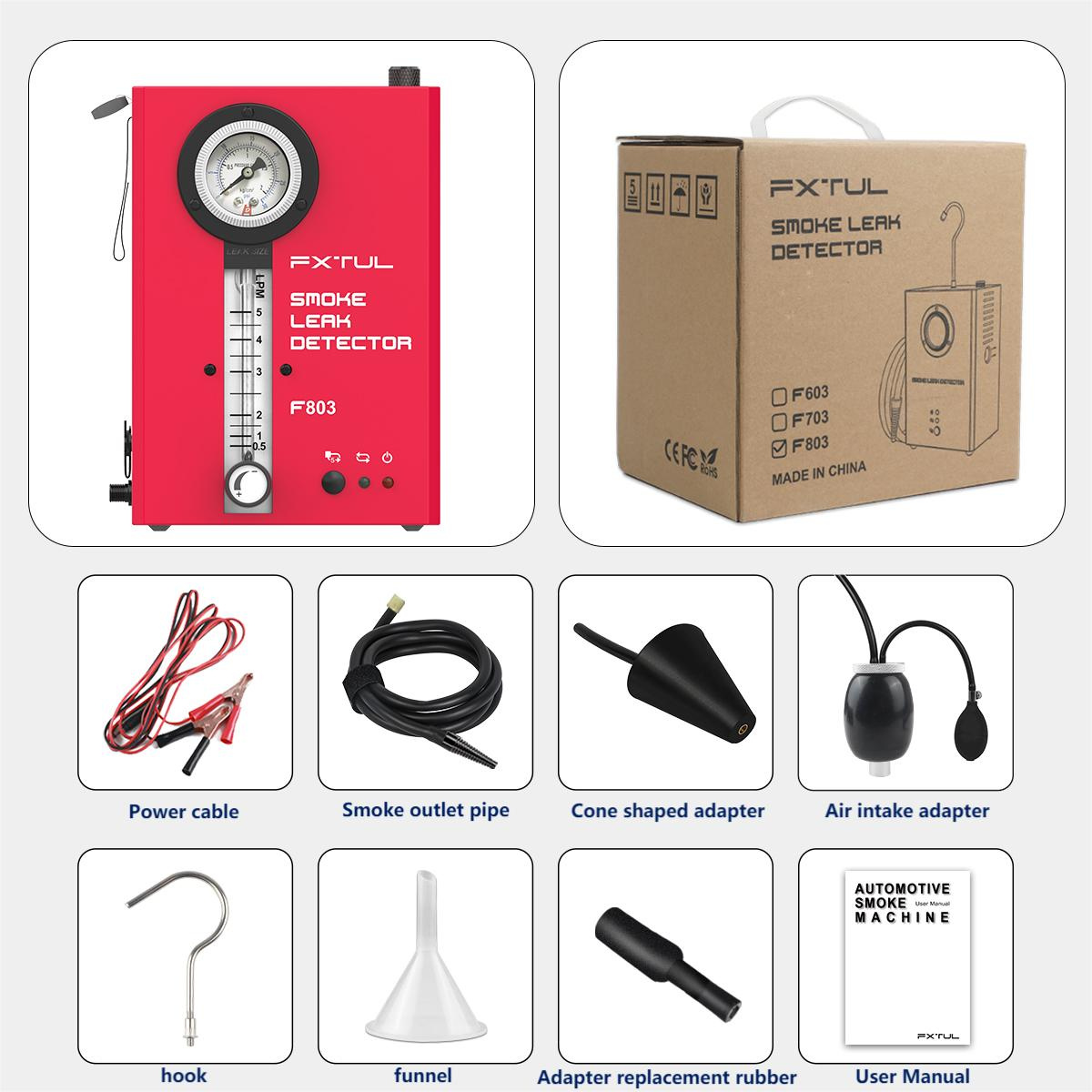
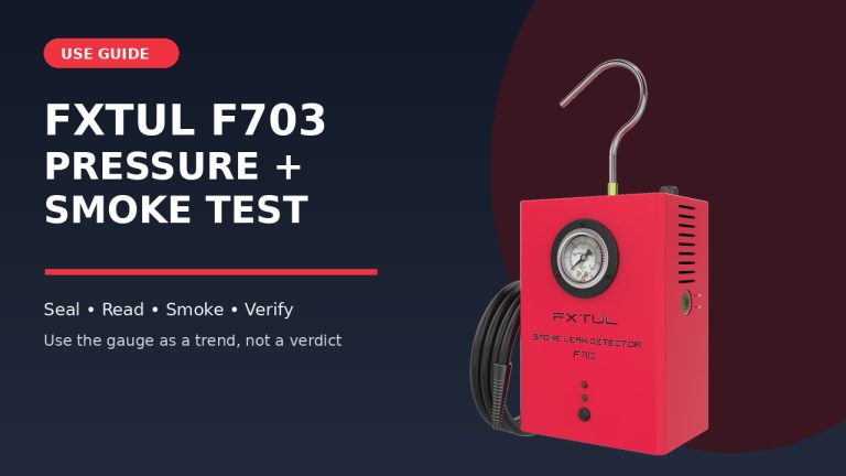
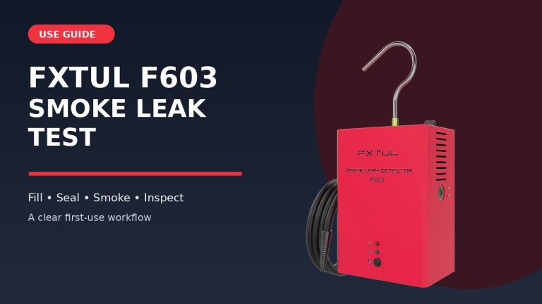
Check the model printed on the front panel. F803 has a round pressure gauge, a vertical flow meter and a separate flow-control valve at the bottom of the front panel. It also has power, working-cycle and alarm indicators. F703 has a pressure gauge but no flow meter or flow-control valve. F603 has neither instrument.
The current F803 listing includes intake, exhaust, fuel-tank, crankcase, turbo, EVAP, pipe and vehicle-sealing applications. That list describes where the model may be used; it does not define how every vehicle must be isolated or pressurized. Use the exact service procedure for the system in front of you, especially for fuel-vapor, crankcase and boosted-air paths.
| What is on your unit? | Correct next step |
|---|---|
| F603; no pressure gauge or flow meter | Use the F603 visible-smoke guide |
| F703; pressure gauge but no vertical flow meter | Use the F703 pressure-trend and smoke guide |
| F803; pressure gauge, vertical flow meter and flow-control valve | Continue with this guide |
| Label is missing, controls do not match, or the machine has been modified | Stop until the exact model and current instructions are confirmed |
Check the kit and prepare the work area
The current kit shows the F803 unit, hanging hook, smoke hose, 12-volt power lead, cone adapter, universal intake bladder with hand pump, replacement rubber, funnel and instructions. Package contents can change, so match the physical items in front of you instead of assuming every regional kit is identical.
Work outdoors or in a well-ventilated repair area. Keep smoking, flames, sparks and other ignition sources away. Let the engine, exhaust, turbocharger and surrounding parts cool before routing a hose or cable. Wear eye protection and gloves suitable for the smoke medium and any residue already inside the selected path.
Have these items ready before connecting power:
- exact vehicle service information for the system, entry point, valve state, designed openings and permitted test pressure;
- a charged 12-volt vehicle battery with identified terminals;
- the F803 hose, power lead, hook, funnel and the correct sealing adapter;
- the smoke medium specified for the unit, with its label readable;
- a bright inspection light, clean cloths and approved caps for the selected path;
- a job note for valve state, entry point, intended openings, flow-control position, pressure trend, flow trend, first smoke exit and repair verification.
Stop: Do not begin with a running engine, an unknown fuel-vapor procedure, a hot exhaust or turbocharger, a damaged cable, an unidentified liquid, or a system whose safe test pressure and isolation state are unknown.
Know what each F803 control tells you
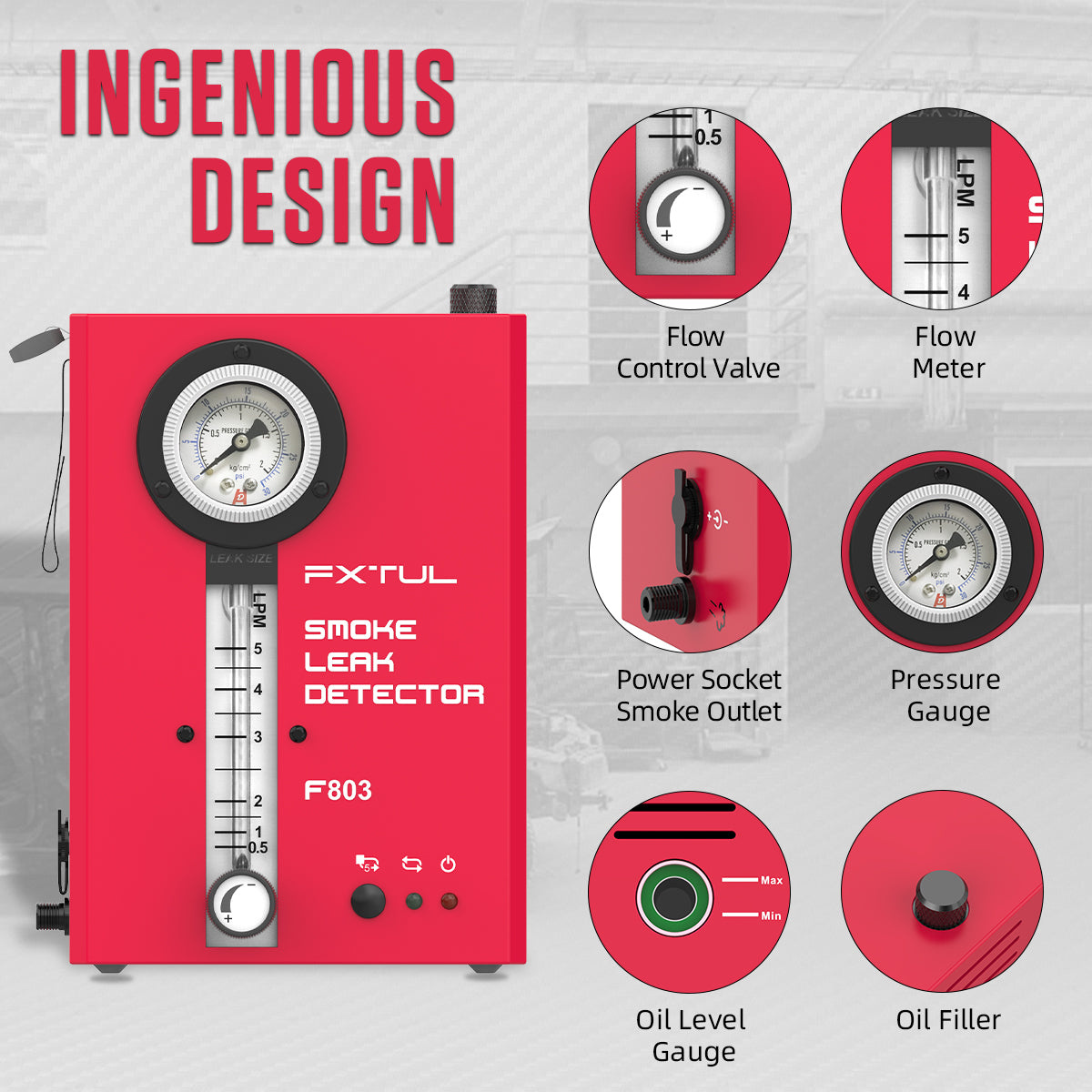
The pressure gauge shows the pressure state in the connected test boundary. The flow meter shows continuing air delivery through that setup. The flow-control valve changes the delivered flow. Read the gauge and flow meter together only after the adapter, caps and system state are stable.
| F803 feature | What it helps you observe | What it cannot decide by itself |
|---|---|---|
| Pressure gauge | Whether pressure builds, stabilizes or changes under one setup | A universal vehicle pass/fail pressure |
| Flow meter | Whether continuing delivery is required under that same setup | A universal leak-size measurement or a failed component |
| Flow-control valve | Lets you establish a conservative, vehicle-permitted test state | The vehicle’s allowable pressure or correct valve position |
| Smoke output | Makes an exit path visible | Whether that opening is designed, whether the adapter leaks, or which nearby part has failed |
| Alarm indicator | Shows that the machine has entered an indicated condition | The exact cause or threshold, because the retained instructions do not define one |
Do not chase a colored gauge zone, a particular float height or maximum machine specification. A steady pressure reading with reduced continuing flow may show that the current boundary is retaining pressure more consistently. Low or slow-building pressure with continuing flow may point to an open path, a poor adapter seal or a designed vent. Those are diagnostic patterns to investigate, not universal verdicts.
Completion check: You can identify the pressure gauge, flow meter, flow-control valve, oil-fill port, oil-level window, smoke outlet, power socket, Start/Stop button and three indicators on your exact F803.
FXTUL F803 step-by-step pressure, flow and smoke test
Step 1: Define one system and its permitted test state
Start with the symptom and the exact vehicle diagram. Name the section being tested, the permitted smoke entry point, every designed opening, the valves that must be open or closed, and the maximum test pressure allowed by the vehicle procedure.
Do not seal a complete unknown system and use the F803 displays to guess the configuration. A vent valve, purge valve, drain, throttle path, pressure-relief device or disconnected service port can be normal in one state and an unintended opening in another. For EVAP work, use the vehicle’s specified service port or approved adapter and its commanded or mechanical vent-isolation method.
Completion check: The job note identifies the system boundary, entry point, valve state, intentionally open paths, permitted caps and pressure limit.
Step 2: Turn the vehicle off, cool it and inspect the path
Turn the engine and ignition off. Secure the vehicle against movement and prevent an unintended start. Let the exhaust, turbocharger and other hot parts cool before placing the hose, power lead or your hands in the work area.
Inspect the planned path before testing. Look for a disconnected hose, split boot, loose clamp, missing cap, pinched seal or damage that already explains the symptom. Verify that the selected adapter will not damage a service port, filler neck or duct.
Stop: Do not route the F803 near a belt, fan, pulley, hot surface or terminal that could energize unexpectedly.
Step 3: Inventory the exact F803 kit
Lay out the F803, hook, smoke hose, 12-volt lead, funnel and the adapter required for the selected entry. Inspect the hose for kinks, cuts or a blocked nozzle. Inspect the power lead for exposed wire, heat damage, corrosion or a weak clamp.
Check the cone and universal intake bladder for cuts, hardening or residue that could prevent a stable seal. If the bladder is required, test its hand pump and relief valve away from the vehicle opening before installation.
Completion check: Every part needed for the selected entry is present, clean, undamaged and matched to the exact F803.
Step 4: Install the hook and keep the F803 upright
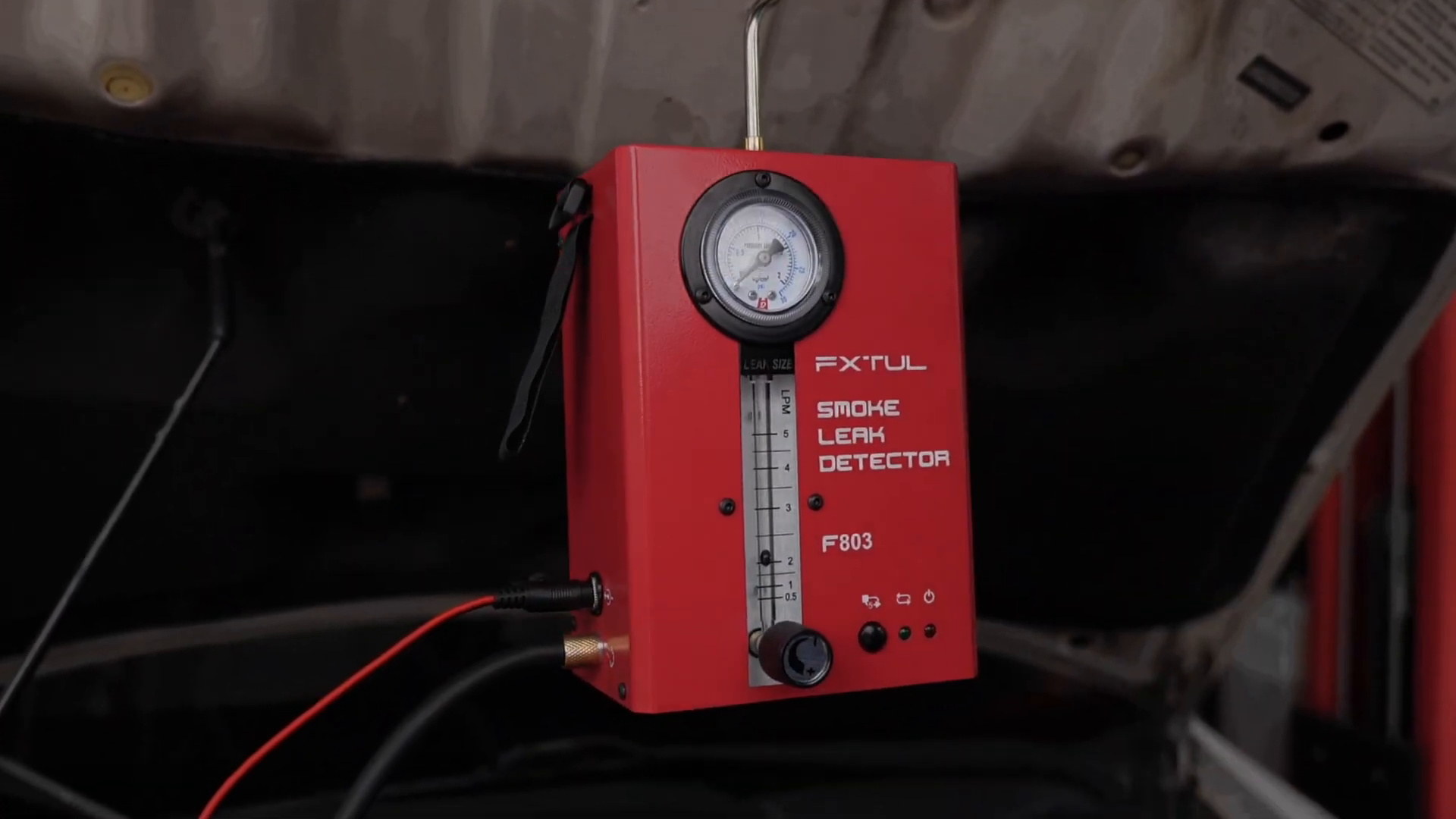
Seat the supplied hook in the top hook port. Stand the unit on a stable surface or hang it from a support that can carry its weight without loading a hose, wire, hood insulation or moving panel.
Keep the case upright through filling, operation, cooling and storage. Do not lay it on its front, back or side. Leave ventilation clearance and enough slack for the hose and cable to curve without kinking.
Completion check: The unit cannot tip, swing into the engine bay or pull sideways on either connection.
Step 5: Connect the smoke hose and device-side power lead
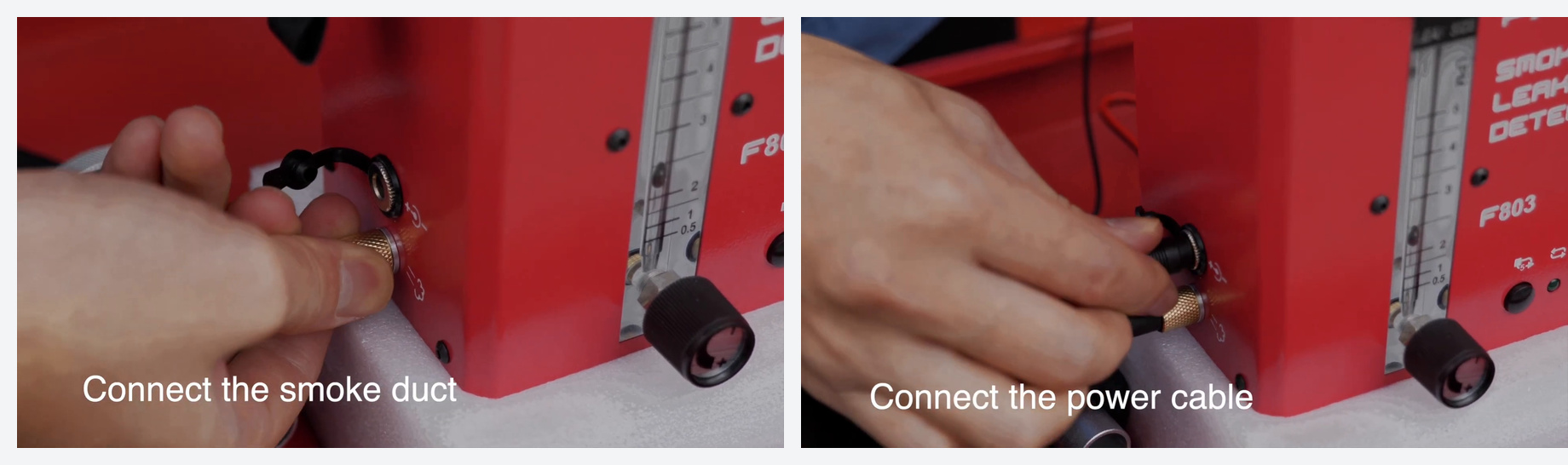
Seat the smoke hose fully on the smoke outlet. Connect the machine end of the power lead to the matching electrical socket. Hold the connector bodies rather than pulling or twisting the wires.
The connector letters in different parts of the shared instructions are inconsistent, so use the physical connector shape, function and demonstrated fit instead of an A/B letter. Leave both battery clamps disconnected while checking the two machine-side connections.
Completion check: The hose and power plug are secure, the hose is open and both battery clamps remain isolated.
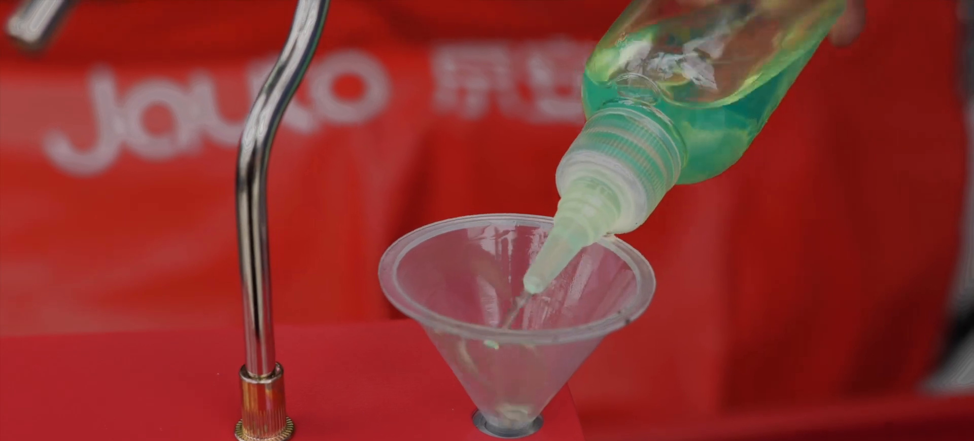
Step 6: Add smoke medium to the oil-level limit
With the F803 unpowered and upright, open the top oil-fill port. Use the funnel or a controlled-tip bottle to add only the smoke medium listed for the unit. The instructions list paraffin, baby oil or mineral oil; do not substitute fuel, solvent, coolant, brake fluid or another workshop liquid.
Watch the side oil-level window while filling. The level must not exceed 2 cm above the bottom of that window. Stop at the level reference instead of copying a fixed milliliter quantity from a generic graphic. Close the fill port and wipe away any spill before power is connected.
If the machine is overfilled, keep it disconnected and correct the level according to the current instructions before use. Never invert a powered or hot unit.
Critical check: The listed fluid is present, the level is within the limit, the fill port is closed and the case is dry.
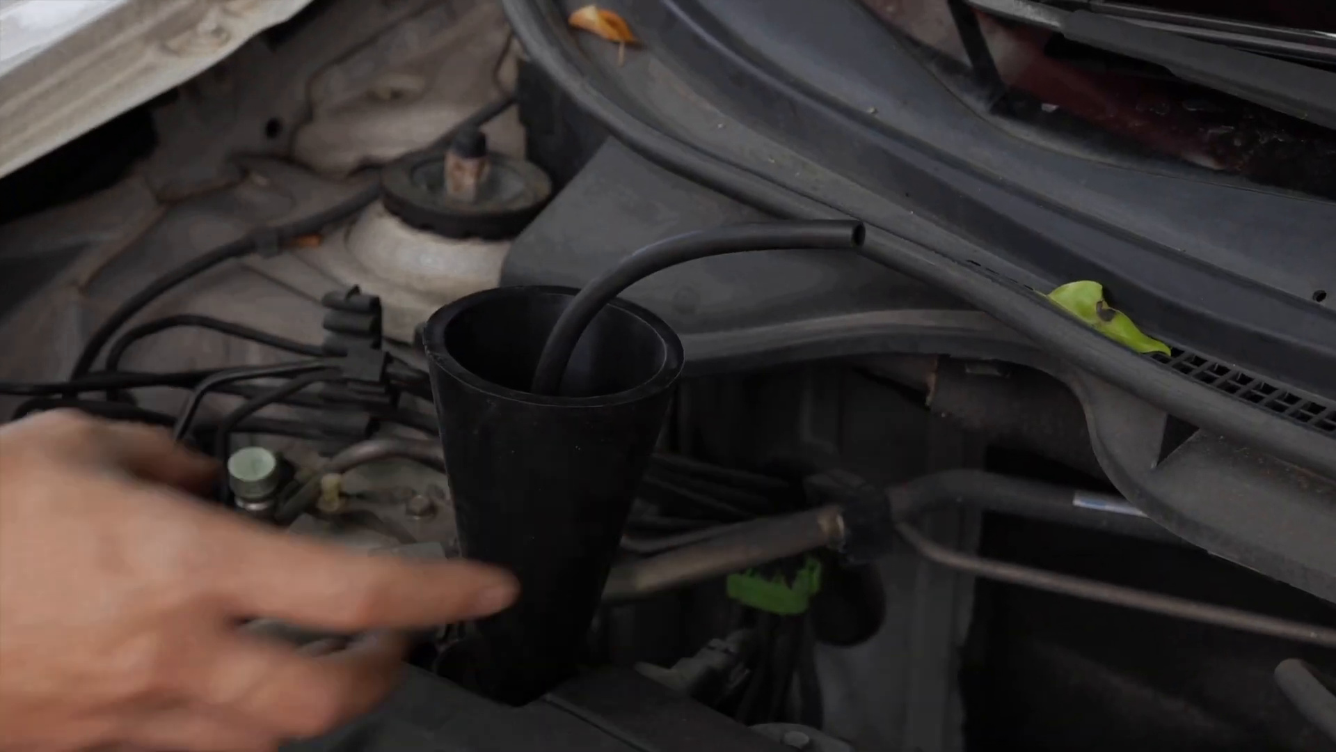
Step 7: Clean and seal the selected entry point
Remove only the connection or access point specified by the vehicle procedure. Wipe the contact surface so grit, a sharp edge or a clamp cannot cut the cone or bladder. Keep debris out of the open path.
For a suitable round opening, seat the cone squarely without forcing it into the duct. For an irregular intake opening, place the universal bladder on a clean surface and squeeze its hand pump until the rubber is secure. Do not overinflate the bladder or place it against sharp or corrosive surfaces.
Support the smoke hose so its weight cannot pull the adapter sideways. Leave the nozzle out until the air-only state and smoke output have been checked.
Completion check: The adapter remains stable with light hose movement and the selected path has the required valve and cap state.
Step 8: Set the flow control conservatively before power-up
Identify the flow-control valve at the bottom of the front panel. Start from a conservative restricted position and follow the vehicle procedure when increasing delivery. Do not assume that fully open is the correct setting.
The machine’s maximum output is a device capability, not permission to apply that pressure to every vehicle system. Never use the control valve to chase a colored gauge band or a particular flow-meter height. If the vehicle information does not define a safe pressure boundary, stop before connecting power.
Completion check: The control position is recorded, the permitted vehicle limit is known and no one will adjust the valve during an observation without restarting the comparison.
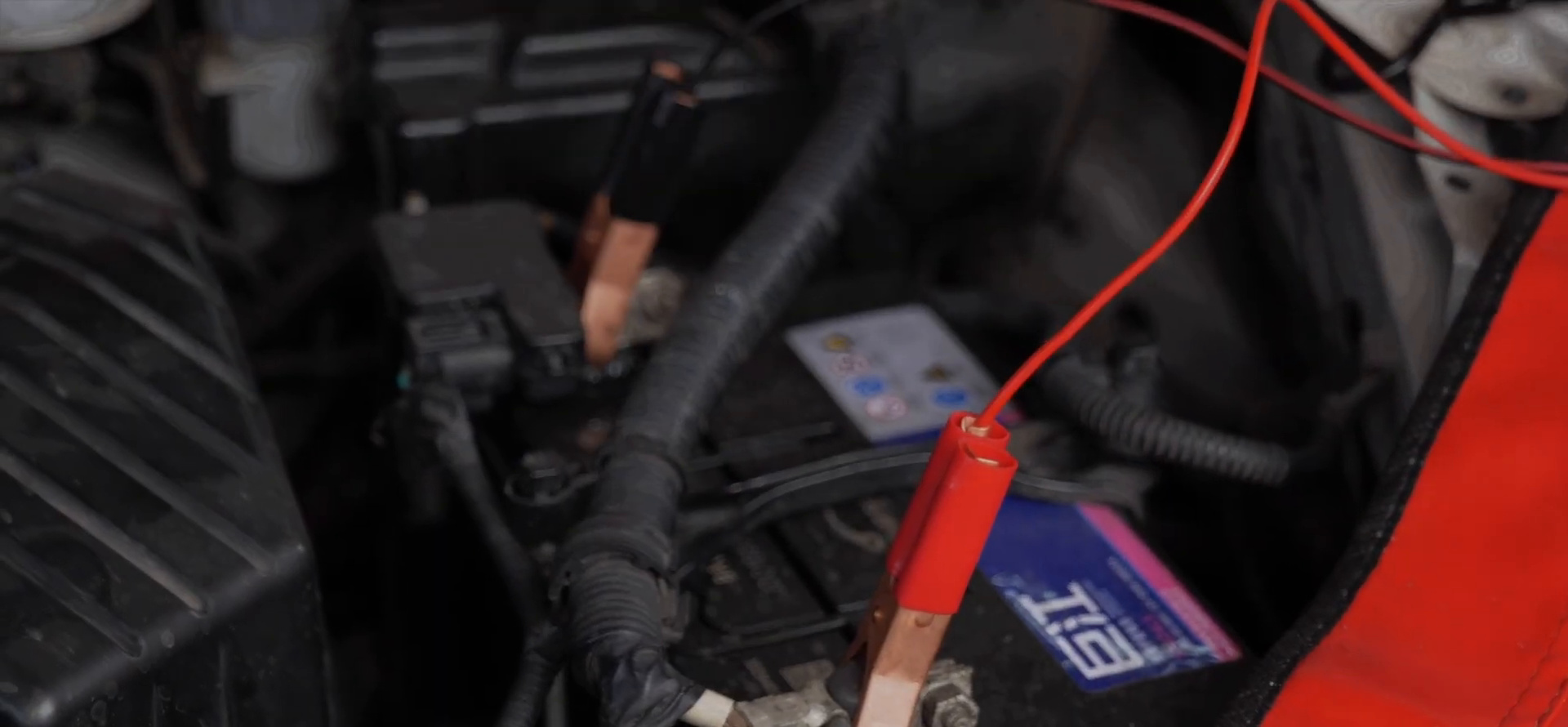
Step 9: Connect the charged 12-volt vehicle battery
Confirm again that the ignition is off. Attach the red clamp to battery positive (+), then the black clamp to battery negative (−). Keep both clamps clear of bodywork, tools and moving parts.
Use a charged 12-volt vehicle battery as specified for the F803. Do not substitute a generic switched DC power supply. Correct power starts the built-in air source for the air-only stage.
Stop: If power is absent, a clamp sparks excessively, a lead heats, the case smells hot or polarity is uncertain, disconnect safely and inspect the power path before continuing.
Step 10: Stabilize the air-only setup for about 30 seconds
Leave smoke off while the built-in pump supplies air. Watch the adapter, every installed cap and any opening that should be closed in the selected vehicle state. Listen for an obvious air escape and confirm that the hose is not kinked.
Allow about 30 seconds for the initial air-stage observation. If air escapes at the cone, bladder or a temporary cap, stop interpreting the instruments. Correct the setup and begin a new observation with the same recorded boundary.
Completion check: The entry seal, valve state, caps, hose route and flow-control position remain unchanged through the observation.
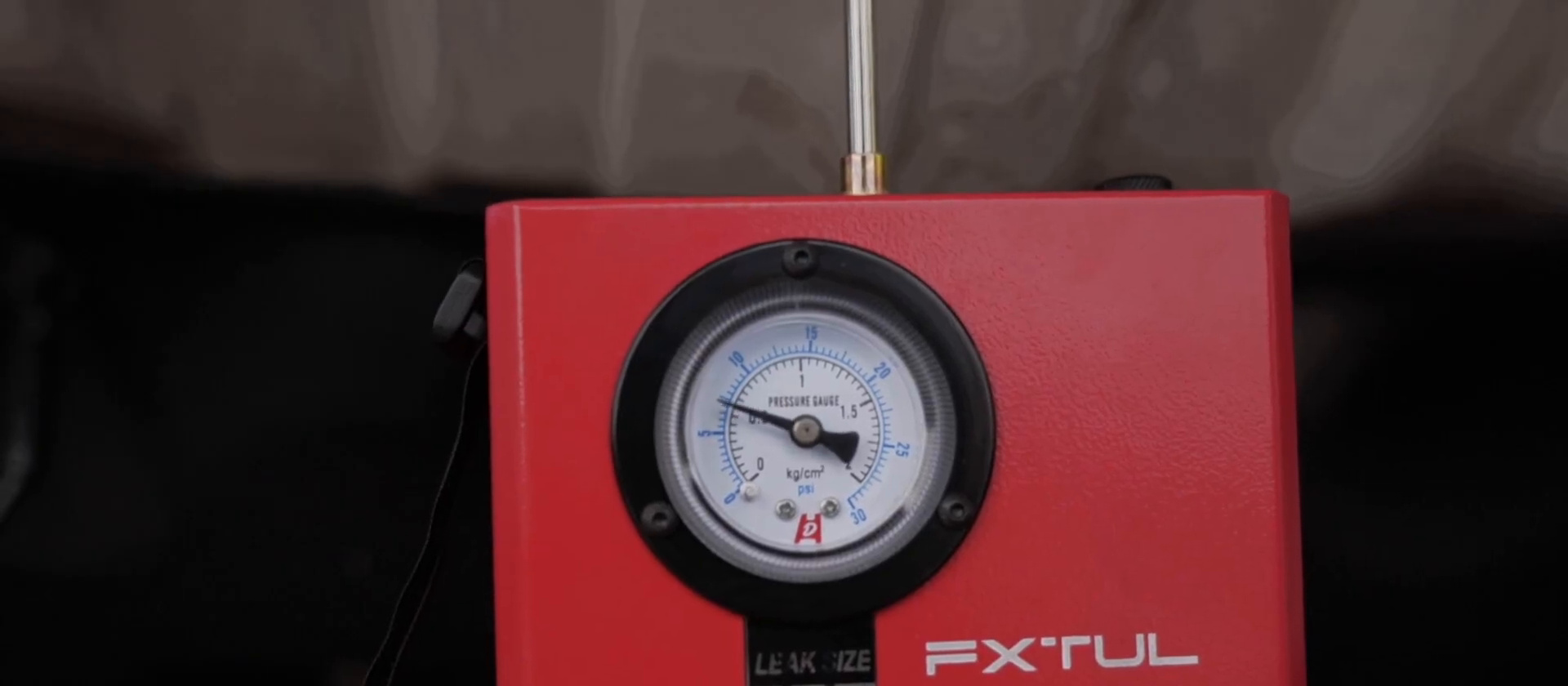
Step 11: Read pressure and flow together
Record the gauge starting position and the flow-meter response, then observe how both change under the stable setup. If the vehicle procedure permits a delivery adjustment, make it gradually, remain below the vehicle limit and start a new timed observation after the control stops moving.
Use the instruments as a paired trend:
| Same-setup pattern | Working interpretation | Next check |
|---|---|---|
| Pressure builds or stabilizes while continuing flow falls | The current boundary is retaining pressure more consistently | Confirm designed openings and proceed to a short smoke-location check; do not call it universally leak-free |
| Pressure stays low or builds slowly while flow continues | Air is leaving the current boundary | Check the adapter, temporary caps, designed vents and valve state before suspecting a vehicle leak |
| Pressure and flow fluctuate between repeats | The test state is not repeatable | Check adapter movement, hose side-load, battery condition and any changing valve or control position |
| Pressure changes but flow indication appears inconsistent | One display alone is not enough to name a cause | Rebuild the setup and repeat; stop if an instrument or control does not respond predictably |
Do not convert a flow-meter position into a leak diameter or a pressure-gauge position into a universal pass/fail result. Record the starting state, observation time and paired trend.
Completion check: The pressure and flow observations refer to the same stable boundary and control position.
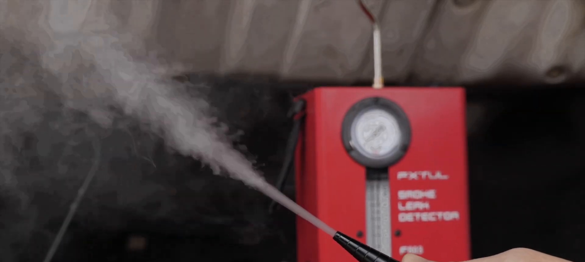
Step 12: Start smoke and confirm output at the nozzle
Press Start/Stop once. The working-cycle indicator should illuminate and the F803 should begin generating smoke. Keep the nozzle outside the adapter only long enough to confirm a steady visible stream.
The smoke cycle stops automatically after five minutes and can be stopped earlier with Start/Stop. A visible stream at the open nozzle proves that the machine is producing smoke; it does not measure vehicle leak size.
Stop: If the machine has power but produces no smoke, stop the cycle, disconnect power, check fluid level and hose routing, and allow the unit to cool before further inspection. Do not force repeated full cycles.
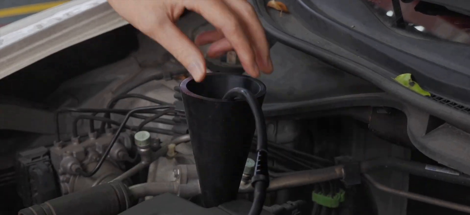
Step 13: Insert the nozzle into the stable adapter
Insert the smoke nozzle through the cone or approved adapter without disturbing its seal. Support the hose so the nozzle does not lever against the opening. Keep the flow-control position, valve state and temporary caps consistent with the recorded air-stage setup.
Watch the adapter first. Smoke escaping around the cone, bladder or service adapter means the entry seal must be corrected before a vehicle joint can be judged.
Completion check: Smoke enters the intended boundary without spilling at the adapter.
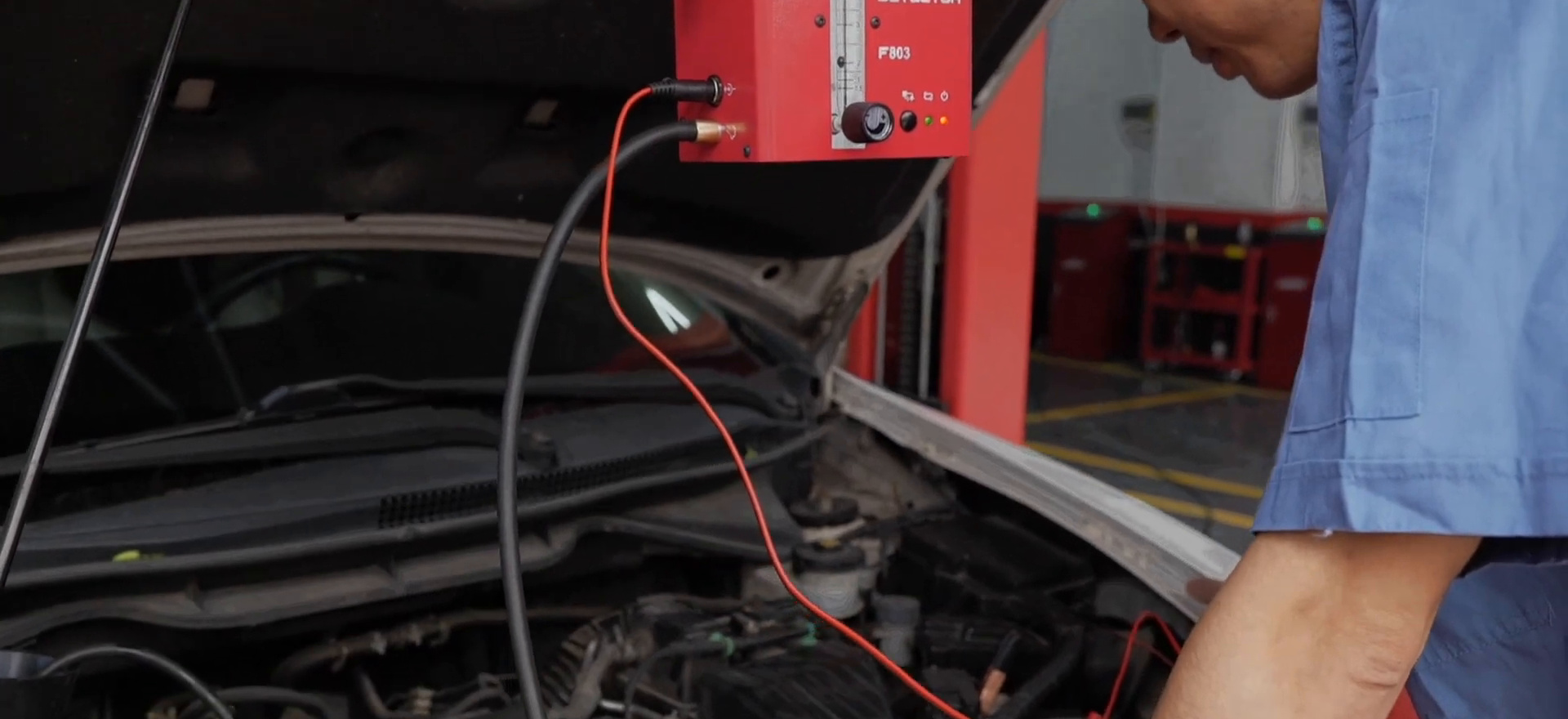
Step 14: Inspect from the entry point outward
Use a bright light and inspect in path order: adapter, nearby joint, clamp, boot, hose, gasket edge, service port and the rest of the selected section. View each area from more than one angle. A thin stream can follow a surface before becoming obvious, while accumulated haze can hide its origin.
Mark the first point where smoke exits into open air. If the area becomes saturated, stop smoke, ventilate, let the haze clear and repeat a shorter observation rather than guessing through the cloud.
Common mistake: Following the largest cloud instead of the first smoke trace. The largest cloud may be where smoke collects, not where it began escaping.
Step 15: Combine the pressure, flow and smoke evidence
Check the adapter and every temporary cap again, then compare the smoke exit with the vehicle diagram. If it is a designed vent, drain or valve opening in the current key-off state, correct the test state only through the service procedure and repeat.
A repeatable pressure-and-flow pattern shows how the defined boundary behaves; the first smoke exit shows where air and smoke leave that setup. Neither proves that the nearest component is the failed part. Inspect the hose, seal, mating surfaces, fasteners and connected components that can create the same path.
Pass condition: The same unintended exit and paired instrument trend can be reproduced after the adapter, designed openings and test-state errors are ruled out.
Step 16: Stop smoke and let residual smoke clear
Press Start/Stop if the smoke cycle is still active. The machine may continue blowing residual smoke from the nozzle after smoke generation stops. Keep the nozzle in a safe ventilated position until the residual output clears; do not cap a hot or smoking nozzle.
If the alarm indicator or another machine state appears abnormal, stop the test, power down and check the setup and current instructions. Do not assign a cause or threshold to the indicator by guesswork.
Completion check: Active smoke generation has stopped and the nozzle is clearing safely away from faces, painted surfaces and ignition sources.
Step 17: Disconnect power, release the adapter and restore the vehicle
Remove the black negative clamp, then the red positive clamp. Disconnect the machine-side lead and smoke hose only after the unit is isolated and cool enough to handle.
Remove the nozzle from the cone or bladder. If the universal bladder was used, hold it securely and press its relief valve until fully deflated before removal. Do not pull an inflated bladder through the opening.
Restore caps, ducts, clamps, service ports and electrical connectors using the vehicle procedure. Keep smoke residue and adapter debris out of the system.
Critical check: Vehicle and F803 power are isolated before the test path is reassembled.
Step 18: Verify the repair under the same conditions
Repair the confirmed cause using the specified part, seal preparation, fastener order and torque. Rebuild the same boundary, use the same entry, valve state, caps, flow-control position and observation time, then repeat the air-stage pressure-and-flow record and a shorter smoke check.
A successful verification has four parts: the paired instrument behavior improves under the same setup, the original unintended smoke exit is gone, the adapter still seals and no new exit appears nearby. Finish with the vehicle’s required operational, scan-tool, monitor or drive-cycle checks; a static pressure-flow-smoke test cannot prove every related symptom is resolved.
Pass condition: The repaired path behaves more consistently under the same permitted test state, remains smoke-tight and passes its separate vehicle service checks.
What the F803 does not decide for you
| Decision | Where the answer must come from |
|---|---|
| Correct connection point | Exact vehicle service information and approved adapter instructions |
| Which vents or valves must be open or closed | The vehicle-specific test procedure |
| Maximum permitted test pressure | The vehicle or component procedure, never the machine maximum by itself |
| Whether visible smoke is normal at a designed opening | The system diagram and current operating state |
| Whether a nearby part should be replaced | Inspection, repeatability and the vehicle’s separate diagnostic checks |
Troubleshoot without forcing a result
| Symptom | Check first | Safe decision |
|---|---|---|
| No power or air stage | Battery state, polarity, clamp contact and lead damage | Disconnect before moving a clamp; do not bypass the lead or use another power-supply type |
| Air runs but pressure does not build | Adapter seal, open hose, designed openings, valve state and a possible gross opening | Correct the defined boundary; do not add shop air or chase a gauge zone |
| Flow continues but no smoke exit is visible | Hidden surfaces, entry seal, designed vent, section volume and lighting | Keep the permitted pressure unchanged; inspect methodically and repeat a shorter clear-area test |
| Pressure or flow changes between repeats | Adapter movement, hose side-load, caps, battery state, control position and observation time | Rebuild one repeatable setup before drawing a conclusion |
| Power is on but no smoke appears | Fluid level, closed fill port, open hose, Start/Stop state and machine temperature | Stop, disconnect and inspect; do not run repeated full cycles without finding the cause |
| Smoke escapes around cone or bladder | Contact surface, adapter position, bladder inflation and hose support | Reseal the entry before judging a vehicle joint |
| Engine bay fills with haze but origin is unclear | Inspection order, lighting, accumulated smoke and entry seal | Stop, ventilate and repeat from the entry point outward |
| Alarm indicator or machine response is unexpected | Power, setup, airflow path, fluid condition and current instructions | Stop and power down; do not invent an alarm meaning or continue until the condition is understood |
| Fluid appears at the case or smoke outlet | Possible overfill, tipped storage or internal leak | Disconnect, keep upright and correct the fluid condition before reuse |
Store and maintain the F803
Let the unit cool, then inspect the hose, nozzle, lead, clamps, hook and adapters. Wipe the exterior and clean the bladder without corrosive liquid. Coil the hose and lead without tight bends and secure them with the straps.
Store the F803 standing or hanging upright—never on its side. Replace old smoke medium with fresh specified medium every three months. Check the level and condition before the next job instead of assuming stored fluid is ready.
Frequently asked questions
Can the F803 be used for an EVAP smoke test?
EVAP is included in the current F803 application list, but the vehicle-specific procedure still controls the service port or adapter, vent and purge state, permitted pressure and final confirmation. Do not improvise those settings from the F803 gauge or flow meter.
Does the flow meter show the exact leak size?
Use it as a comparative indication of continuing delivery under one controlled setup. The retained instructions do not provide a universal float-position-to-leak-size rule, so combine its trend with pressure behavior, visible smoke, the system diagram and a repeat test.
How much smoke fluid should I add?
Use the oil-level window, not a copied fixed volume. With the unit upright and disconnected, add only paraffin, baby oil or mineral oil and do not let the level exceed 2 cm above the bottom of the window.
Can I power the F803 from a bench supply?
Use a charged 12-volt vehicle battery with red connected to positive and black to negative. The instructions prohibit a switched DC power supply.
Why does smoke continue after I press Start/Stop?
The machine can blow residual smoke from the nozzle after active smoke generation stops. Leave the nozzle in a safe ventilated position until the output clears, then disconnect and store the unit upright.
What a complete F803 job looks like
A complete job is not “the gauge moved,” “the float changed” or “smoke came out.” You identified the exact F803, defined one vehicle-supported low-pressure boundary, recorded its openings and valve state, used the correct smoke medium and level, powered the unit from a 12-volt vehicle battery, established a conservative permitted flow, read pressure and flow together, traced the first unintended smoke exit and confirmed the repair under the same conditions.
That sequence is the practical value of the F803. Pressure shows how the defined boundary responds, continuing flow shows what the machine must keep supplying, and smoke makes the exit path visible. Keep the boundary and control position constant, and the three observations become evidence instead of reasons to guess at parts.


Comments 0
Questions, fixes, and real-world diagnostic notes from readers.
Be the first to share a diagnostic result or ask a follow-up question.