
How to Use the AUTOOL EM355: Programming Power Supply, Charging and Restoration

The AUTOOL EM355 supports three workshop tasks: it can hold vehicle voltage during a programming session, charge supported 12-volt lead-acid batteries, or run an off-vehicle battery-restoration cycle. It does not program an ECU by itself. The safe workflow is to identify the exact task, verify the battery and mains supply, connect with the unit switched off, select the matching mode, watch the screen throughout the job, and use Stop before removing the clamps.
Use this guide with the manual supplied with your machine and the vehicle or battery procedure for the job. The EM355 manual says trained and qualified personnel should operate the unit; programming voltage, vehicle preparation and the actual flashing sequence must come from the vehicle manufacturer or approved programming procedure.
Updated: August 27, 2026.
In this guide
- Choose the right EM355 mode first
- Before you connect anything
- Common setup and connection
- Use Programming Power Supply mode
- Use Fast Charging mode
- Use Battery Restoration only off the vehicle
- Alerts, shutdown and storage
- Five mistakes that create most EM355 problems
- EM355 questions answered
- Final operating checklist
Choose the right EM355 mode first
| Your job | Select on the EM355 | The deciding information | Do not use it for |
|---|---|---|---|
| Hold vehicle voltage during diagnosis, coding or programming | Programmable Power Supply → Fixed Mode or Adjustable Mode | The exact vehicle or programming procedure; Fixed is 14 V, Adjustable is 10.8–16.0 V | Choosing a target voltage by guesswork or performing the ECU flash itself |
| Charge a supported battery while it remains in the vehicle | Fast Charging → Battery Charging → In-car Charging | Battery label must identify Standard lead-acid, AGM flat plate, AGM spiral or GEL | EFB, lithium or an unsafe/damaged battery |
| Charge a supported battery after it is disconnected or removed | Fast Charging → Battery Charging → External Charging | Battery label must identify Standard lead-acid, AGM flat plate, AGM spiral, EFB or GEL | Lithium or an unidentified battery |
| Attempt restoration of a severely discharged supported lead-acid battery | Fast Charging → Battery Restoration | Battery removed from the vehicle, correct battery type and acceptable physical condition | A universal battery repair, an in-vehicle task or a battery with an internal short |
The delivered unit’s nameplate is the final authority for mains input. The manual shows regional 110-volt and 220-volt versions, while some product imagery shows only 220 volts. Do not assume that every EM355 is universal-voltage.
Before you connect anything
- Read the delivered manual and keep it at the work area. A current copy can also be located in the AUTOOL manual center.
- Identify the battery chemistry from its label; appearance alone is not enough.
- Confirm that the battery is rechargeable, visually intact and free from an internal-short indication.
- Match the grounded outlet, input voltage and fuse to the EM355 nameplate. Do not defeat the protective ground or use a damaged extension or power cable.
- Work indoors in a dry, clean and well-ventilated area. Keep sparks, flames, corrosive material and conductive debris away.
- Wear eye protection and insulated gloves. Keep other people and animals clear of the work area.
- Inspect the unit, clamp lead, connector, clamps and power cord. Do not use damaged equipment.
- Keep the machine at least 50 cm from nearby objects, away from the battery and with both cooling fans unobstructed.
- Do not start a charging task above 36°C ambient. Disconnect immediately if battery temperature rises above 45°C.
Stop: Do not continue if the battery is cracked, leaking, visibly swollen, internally shorted or otherwise unsafe; if a cable or clamp is damaged; if the input supply does not match the nameplate; or if the EM355 produces smoke, an unusual smell, unusual noise or excessive heat.
Common setup and connection
Step 1: Identify every control before connecting
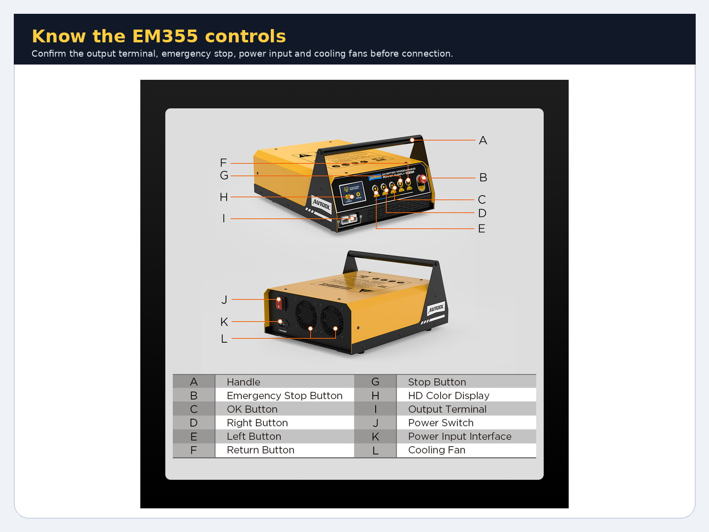
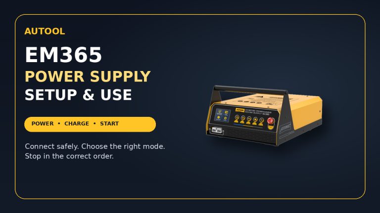
Locate the front output terminal, HD color display, Left, Right, OK, Stop and Return keys, and the red emergency-stop button. At the rear, identify the main power switch, power-input interface and both cooling fans. The navigation pattern is simple: Left or Right changes the highlighted option, OK enters or confirms it, Return moves back, and Stop ends the active output normally.
Completion check: You can point to the normal Stop key and emergency-stop button without searching, and neither cooling fan is obstructed.
Step 2: Place the EM355 away from the battery
Put the unit on a stable, dry surface; never set it directly on top of the battery. Use the available clamp-lead length to keep the battery and machine apart. Route the leads so they cannot be pinched, pulled, driven over or placed near heat and moving parts.
Completion check: The unit is stable, ventilated and separated from the battery, with a clear route to the clamps and outlet.
Step 3: Verify the delivered power version
Read the input rating on the exact unit in front of you. Confirm that the grounded outlet and circuit protection match it before inserting the power cord. If the nameplate, plug, outlet or supply is uncertain, pause rather than trying the connection.
Common mistake: Treating a specification seen online as proof that the delivered EM355 accepts both 110 and 220 volts.
Completion check: The outlet voltage, ground, fuse and plug are confirmed against the delivered nameplate.
Step 4: Confirm battery type and task conditions
Read the battery label and record whether it is Standard lead-acid, AGM flat plate, AGM spiral, GEL or EFB. The EM355 is not a lithium charger. For programming support, begin with the vehicle battery fully charged. For EFB charging, disconnect or remove the battery and use External Charging. For restoration, remove the battery from the vehicle regardless of type.
Stop: Do not infer chemistry from the battery case shape, and do not select a nearby type just to make the menu proceed.
Completion check: Battery chemistry, installation state and intended mode agree with the mode table above.
Step 5: Connect the output lead with power off
With the rear power switch off and the EM355 not yet connected to mains, seat the supplied clamp-lead connector fully in the front output terminal. Inspect the lead once more so the positive and negative paths are easy to follow.
Completion check: The output connector is fully seated, the cable is undamaged and the clamps cannot touch each other.
Step 6: Attach the clamps with correct polarity
Follow the vehicle or battery service procedure for safe terminal access. Connect the red positive clamp to the identified positive terminal and the black negative clamp to the approved negative connection point. Keep your face away from the battery and make the final connection without creating a spark near a venting battery.
Stop: If polarity or the approved negative connection point is uncertain, do not energize the EM355.
Completion check: Both clamps grip clean, solid connection points and cannot rotate or contact adjacent metal.
Step 7: Connect mains, switch on and pass the first screen check
Connect the verified mains lead, then use the rear power switch to turn on the EM355. A short fan self-test is normal; the manual says the fans may run for about two minutes and then stop. Confirm that the display starts normally and does not show Battery Not Connected, Reverse Polarity, Temperature Abnormality or another alert.
Stop: If an alert appears, do not select a work mode. Use the alert section below to correct only the external condition described by the manual.
Completion check: The main menu displays Programmable Power Supply, Fast Charging and Settings with no active alert.
Use Programming Power Supply mode
The AUTOOL EM355 can provide a stable vehicle supply while a separate scan tool, computer and approved procedure perform diagnosis, coding or programming. The EM355 should not decide the voltage or replace vehicle-specific preparation.
Step 8: Choose Fixed or Adjustable mode
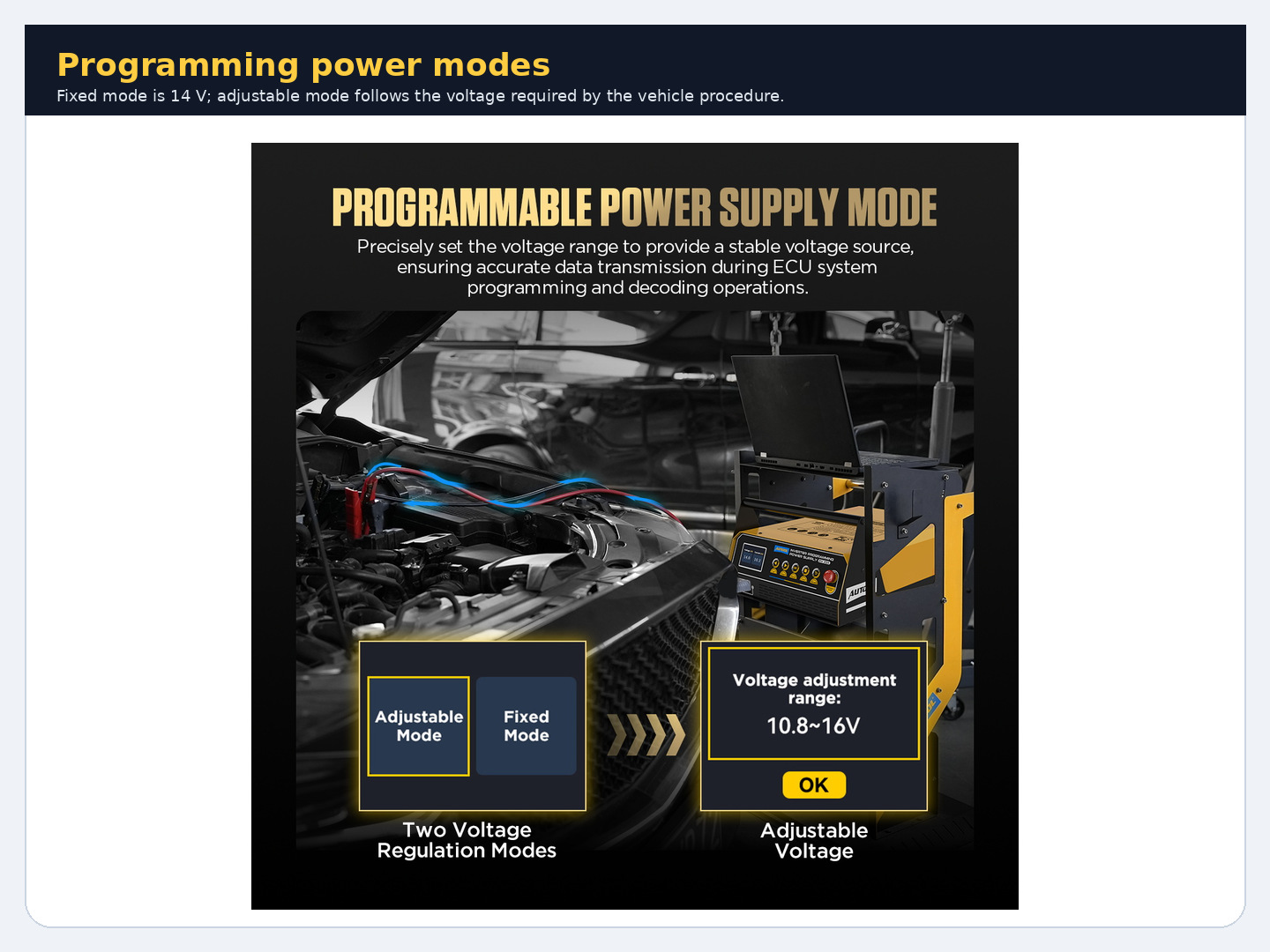
At the main menu, highlight Programmable Power Supply and press OK. Choose Fixed Mode only when the procedure calls for the EM355 fixed 14-volt output. Choose Adjustable Mode when the exact procedure specifies another target within 10.8–16.0 volts; use Left and Right to set that value, then press OK to continue.
Common mistake: Choosing the highest available voltage because it appears to offer more support. Voltage is a vehicle-procedure value, not a performance setting.
Completion check: The mode and displayed target match the written programming procedure exactly.
Step 9: Confirm connection and battery-capacity prompts
Read the on-screen prompt before starting output. Verify again that the clamps remain tight, polarity is correct and the vehicle battery has sufficient capacity and charge for the session. Complete every vehicle-side preparation required by the programming procedure before confirming output.
Stop: Do not begin if the battery is not fully charged, the vehicle setup is incomplete, the programming target is uncertain or clamp movement is possible.
Completion check: Vehicle preparation is complete and the EM355 prompt can be confirmed without an assumption.
Step 10: Start output and monitor the whole session
Press OK to start the selected supply mode. Watch voltage, current, battery temperature, cable position and the vehicle/programming tool. Keep the unit attended and its fans clear. The manual lists 120 A programming output, but also says maximum current may be available for about three minutes before thermal control can reduce output to 50 A until the unit cools; plan the session from the vehicle’s real demand, not the headline number.
Stop: End the task if the programming procedure tells you to stop, voltage becomes unsuitable, an EM355 alert appears, the battery exceeds 45°C, or you notice smoke, odor, abnormal noise or excessive heat.
Completion check: The separate programming or diagnostic procedure finishes normally while EM355 voltage remains within that procedure’s required range.
Use Fast Charging mode
Step 11: Choose In-car or External charging
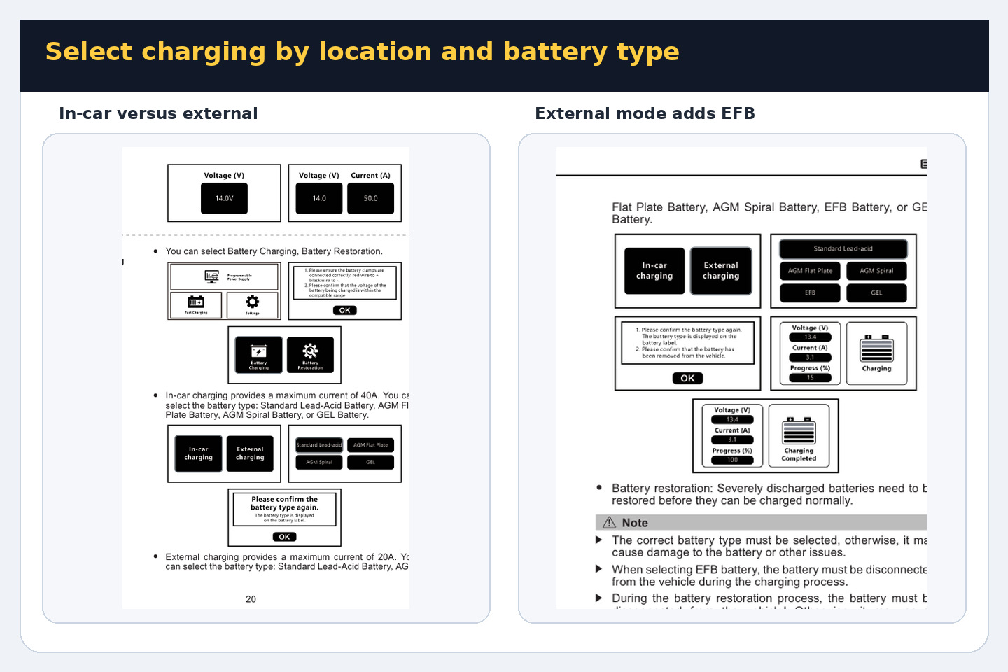
From the main menu, select Fast Charging, press OK, choose Battery Charging, then select the location. Use In-car Charging only for an installed Standard lead-acid, AGM flat plate, AGM spiral or GEL battery when the vehicle procedure permits charging in place. Use External Charging for a disconnected or removed battery; EFB is available only here.
The current manual contains two different current descriptions: its specification table lists 20 A/12 V lead-acid charging, while the operating page labels In-car Charging as a maximum of 40 A and External Charging as a maximum of 20 A. Treat 20 A/12 V as the published specification and the 40 A figure only as the manual’s label for that specific mode—not as a promised continuous output. Select the mode by battery location and chemistry, never by chasing the larger number.
Completion check: The selected location matches the battery’s actual connection state and EFB is not selected in-car.
Step 12: Select and confirm the exact battery type
Use Left and Right to highlight the chemistry printed on the battery label, then press OK. Read the confirmation screen, compare the displayed type with the physical label, and confirm again only when they match.
Stop: If the label is missing, contradictory or identifies a lithium chemistry, do not begin charging with the EM355.
Completion check: The confirmation screen and battery label show the same supported chemistry.
Step 13: Monitor charging to a valid end state
Start the cycle and remain at the work area. Watch displayed voltage, current and progress as well as battery temperature and physical condition. Normal automatic completion is the Charging Completed screen. If you must stop earlier, press Stop first and wait for output to end before touching the clamps.
Stop: Stop for an alert, gas or heat behavior outside normal charging conditions, leakage, swelling, battery temperature above 45°C or any unsafe change in the work area.
Completion check: The EM355 displays Charging Completed, or an intentional early stop has ended output before disconnection.
Use Battery Restoration only off the vehicle
Step 14: Prepare an off-vehicle restoration task
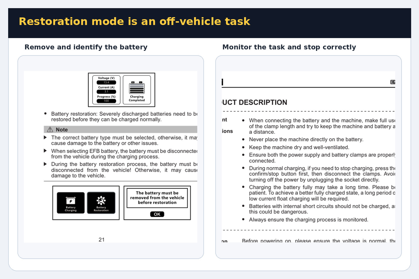
Switch off, disconnect and remove the battery using the vehicle procedure, then place it in an open, shaded and well-ventilated area. Confirm its supported lead-acid type and inspect it again. Restoration may help some deeply discharged or sulfated batteries, but the manual says the result depends on battery condition and warns that the process may cause fluid loss or drying.
Stop: Do not run Restoration with the battery connected to the vehicle, on an internally shorted or physically unsafe battery, or as a substitute for proper battery diagnosis.
Completion check: The battery is isolated from vehicle electronics, correctly identified, stable and safe to monitor.
Step 15: Select Restoration and judge the screen result
Reconnect the isolated battery by the common connection steps, select Fast Charging, choose Battery Restoration and confirm the removal prompt. Monitor the entire cycle. The EM355 may display Restoration Completed, Restoration Failed or No Battery Restoration Required; treat each as a device result, not proof that the battery can safely meet vehicle load or service requirements.
Common mistake: Repeating restoration cycles to force a pass or promising that a completed screen means the battery is as good as new.
Completion check: The unit reaches a named end screen, output stops, and the battery is evaluated separately before being returned to service.
Alerts, shutdown and storage
Step 16: Respond to an alert without bypassing it
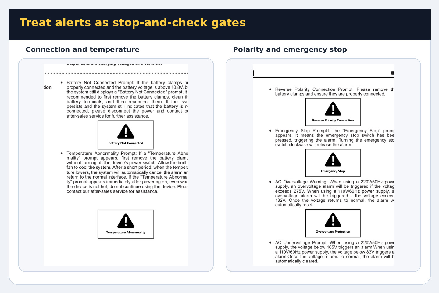
If Battery Not Connected appears, stop and inspect the clamps and clean, sound terminal contact before one careful reconnection. For Reverse Polarity, remove the clamps with output stopped and reconnect correctly. For Temperature Abnormality, follow the manual’s instruction to remove the battery clamps without switching off the machine so the fan can cool the unit; do not continue if the warning appears immediately on a cold unit. If Emergency Stop appears, verify why the red control was pressed and rotate it clockwise to release it only after the work area is safe.
AC overvoltage, undervoltage, input overcurrent, output overvoltage, output overcurrent, leakage and short-circuit messages are stop conditions. Correct only an obvious external supply, connection or cable problem; do not open the EM355 or repeatedly reset a persistent alert.
Stop: Persistent, unexplained or immediate cold-start alerts require the unit to remain out of service until qualified support checks it.
Completion check: The cause is identified and corrected externally, or the unit is safely removed from service without bypassing protection.
Step 17: End the selected function normally
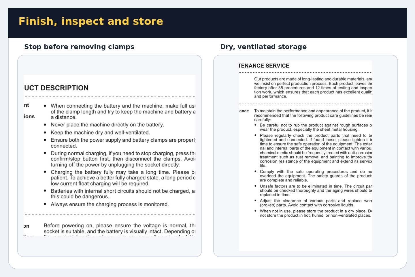
When the programming-support task is complete, follow the vehicle procedure for ending its session, then press Stop on the EM355 and wait for output to cease. During charging, use the same Stop-first rule if you are ending before Charging Completed. Keep monitoring until the active-output screen has ended.
Common mistake: Pulling the mains plug to stop normal charging. The manual specifically calls for Stop/confirm before clamp removal.
Completion check: No active mode remains and the display confirms that output has ended.
Step 18: Shut down in the correct order
After output has stopped, remove the battery clamps following the vehicle or battery procedure, turn off the rear power switch, and unplug the power cord. Inspect the cables, clamps, output connector and housing. Arrange the leads without tight bends, then store the EM355 dry, clean and ventilated, away from children, corrosive liquids, heat and humidity.
Stop: Do not store or reuse the unit if a cable is loose or damaged, the enclosure has been struck, or operation produced an unresolved smell, noise, heat or protection alert.
Completion check: The unit is de-energized, disconnected, inspected and stored with no cable strain or ventilation obstruction.
Five mistakes that create most EM355 problems
- Treating the EM355 as the ECU programmer instead of the support supply.
- Guessing programming voltage rather than reading the exact vehicle procedure.
- Selecting battery chemistry from appearance, especially choosing EFB in-car or attempting lithium charging.
- Running Restoration while the battery remains connected to vehicle electronics.
- Removing clamps or pulling the mains plug before using Stop to end normal output.
EM355 questions answered
Can EM355 charge a lithium battery?
No. The EM355 menu and current manual cover supported 12-volt lead-acid types. A lithium battery requires equipment and a procedure explicitly approved for its chemistry and battery-management system.
Should I use Fixed or Adjustable mode for ECU programming support?
Use the mode required by the exact programming procedure. Fixed Mode supplies 14 V. Adjustable Mode lets a qualified operator select 10.8–16.0 V, but the range is not permission to choose a voltage without vehicle information.
Why is EFB missing from In-car Charging?
The manual limits EFB to External Charging with the battery disconnected from the vehicle. Do not work around that menu boundary.
Does Restoration prove the battery is healthy?
No. Restoration Completed is the end of the EM355 cycle, not a load, capacity or vehicle-serviceability test. Diagnose the battery before returning it to service.
What if an alert returns after I correct the connection?
Stop using the unit. A persistent or unexplained alert is not a prompt to open the case or bypass protection; keep the EM355 out of service until qualified support checks it.
Final operating checklist
- Task, vehicle procedure and battery chemistry identified.
- Delivered nameplate matched to a grounded outlet and fuse.
- EM355 dry, ventilated, stable and separated from the battery.
- Cables, clamps, polarity and approved connection points checked.
- Correct mode, location, chemistry and—when applicable—programming voltage confirmed.
- Screen, battery temperature and work area monitored throughout.
- Any alert treated as a stop-and-check condition.
- Stop used before clamp removal; rear switch and mains disconnected afterward.
- Battery result verified separately before programming or returning the battery to service.
The EM355 becomes straightforward when its three functions stay separate: use exact vehicle information to control programming support, use battery location and label to control charging, and reserve restoration for a removed battery with realistic expectations. That decision-first approach protects the vehicle, the battery and the power supply while giving every session a clear pass or stop point.



Comments 0
Questions, fixes, and real-world diagnostic notes from readers.
Be the first to share a diagnostic result or ask a follow-up question.