
How to Use the AUTOOL LM120 Digital Manifold Gauge

Use the AUTOOL LM120 by verifying the vehicle refrigerant, closing both manifold valves, inspecting every hose and fitting, installing four AA batteries, selecting the matching refrigerant and units, and zeroing both disconnected pressure channels at atmosphere. Connect it only through the vehicle service procedure, then record both pressures and the available pipe-temperature data under one stable test condition.
The LM120 is a dual-channel digital manifold with 89 refrigerant pressure-temperature datasets, relative-vacuum and timed pressure-change modes. It can support A/C diagnosis and controlled service work, but it cannot identify refrigerant, choose a charge amount, prove deep evacuation or certify that a system is leak-free.
Updated August 27, 2026.
In this guide
What the LM120 displays
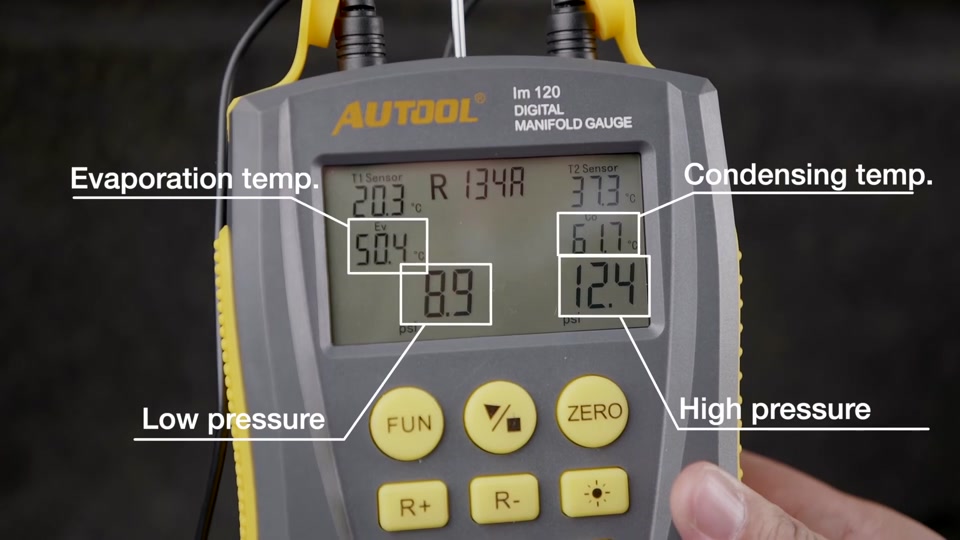
The AUTOOL LM120 measures low- and high-side gauge pressure. After you select the correct refrigerant, it converts those pressures to evaporation (EV) and condensation (CO) saturation temperatures. With compatible probes attached to the correct pipes, it can also show pipe temperatures and calculate superheat (SH) and subcooling (SC).
The shared LM120/LM120+ manual lists a -101 kPa to 6 MPa pressure range, but the included-hose working limit can be lower. The lowest-rated manifold, hose, coupler, adapter and vehicle component controls. The refrigerant list is reference data, not automatic proof of system or accessory compatibility.
Before you start
Open the AUTOOL manual download center and match the shared LM120/LM120+ manual to the exact LM120 in front of you. Obtain verified refrigerant identity, port layout, operating test, target data, recovery and evacuation method from the vehicle procedure. Confirm which hoses and probes were actually delivered.
Use ventilation, eye and hand protection, rated low-loss couplers and compliant recovery/service equipment. Keep hoses and probe leads clear of fans, belts, exhaust heat and electrical terminals.
Stop: Do not connect an unknown or contaminated refrigerant system, vent refrigerant to purge a hose, exceed the lowest component rating, or open either manifold valve without knowing exactly where the center path leads.
Understand the LM120 controls
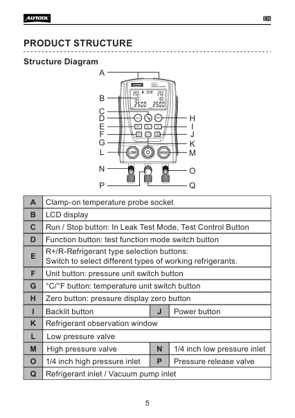
The blue knob controls the low-side path and the red knob controls the high-side path. The lower fittings are low side, center service/vacuum source and high side. The front keys select Function, Run/Stop, refrigerant R+/R-, pressure Unit, °C/°F, Zero, backlight and power. The screen changes meaning by mode, so confirm the visible mode before interpreting a number.
LM120 step-by-step operating procedure
Step 1: Define the exact task
Choose running pressure/temperature diagnosis, procedure-controlled evacuation observation or an isolated pressure-change test. Record refrigerant, connection diagram, required system state, target values, stabilization time and finish procedure.
Completion check: Every connection and pass/fail value comes from the exact vehicle or equipment information.
Step 2: Inspect the LM120 and pressure path
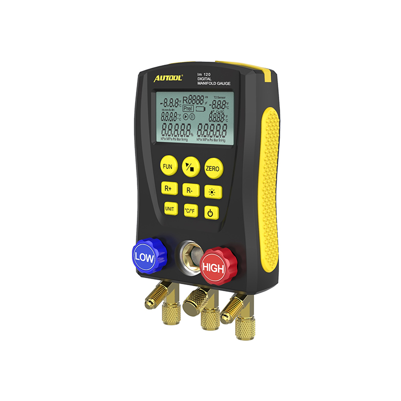
Close both valves. Inspect the screen, housing, sight window, pressure-release hardware, probe socket, brass threads, hoses, couplers, gaskets and valve stems. Replace damaged or hardened parts and confirm working ratings.
Completion check: The complete pressure path is clean, intact, compatible and closed.
Step 3: Install four AA batteries
Install four matched 1.5 V AA/LR6 batteries with correct polarity. Power on and check the low-battery icon, complete screen segments, backlight and buttons.
Completion check: The display is stable and the battery state can support the full test.
Step 4: Keep both channels at atmosphere
Before connection, leave both pressure inlets open to clean atmospheric pressure with both control valves closed. Do not trap pressure in a hose or apply vacuum while establishing zero.
Completion check: Neither channel is connected to a pressure source.
Step 5: Select refrigerant and units
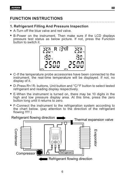
Use R+/R- to select the refrigerant verified from vehicle information. Choose the pressure and temperature units used by the service procedure. Do this before recording measurements so EV, CO, SH and SC are based on the correct dataset.
Completion check: Refrigerant and units match the written job sheet exactly.
Step 6: Zero both pressure channels
With both inputs still at atmosphere, hold Zero until residual digits return to zero. If a channel remains offset, allow the instrument to stabilize and inspect for trapped pressure or damage.
Completion check: Both open-air channels read zero before any service connection.
Step 7: Connect and position the temperature probes
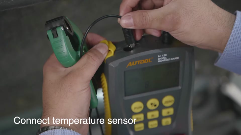
Connect only probes compatible with the exact delivered LM120. Clamp them at the pipe locations specified by the vehicle procedure, map each channel to its pipe, and route leads away from heat and movement. Stable metal contact matters more than clamp color.
Completion check: Each displayed probe value belongs to a named, documented pipe location.
Step 8: Hang the manifold and route hoses
Hang the LM120 upright where the display is visible. Trace the blue hose to the verified low-side port, red to high side and center path to the required recovery, vacuum or charging equipment. Follow the vehicle and coupler instructions for connection order.
Stop: If a coupler resists, a port leaks or hose identity is uncertain, isolate and correct the setup.
Completion check: Every hose is traced end to end and both manifold valves remain closed.
Step 9: Establish the specified operating condition
For diagnosis, place the vehicle in the exact engine-speed, blower/load, door, fan and ambient condition required by service information. Observe from a safe position and allow pressure, temperatures and compressor operation to stabilize.
Completion check: The system condition is stable and fully documented before the reading is captured.
Step 10: Capture the complete running data set
Record low pressure, high pressure, EV, CO, both pipe temperatures when available, SH and SC. A plausible pressure can still be misleading if refrigerant selection, probe placement, airflow, compressor command or test condition is wrong.
Completion check: All values were captured together under one condition and are compared with the vehicle’s specified window.
Step 11: Interpret evidence before moving refrigerant
Use the vehicle diagnostic sequence to assess airflow, fan operation, compressor control, restrictions, sensor data and refrigerant condition. Do not add or remove refrigerant merely to make one pressure look familiar. Charge by the specified process and mass with compliant equipment when service is actually required.
Completion check: Setup and system-control causes are separated before a charge decision.
Step 12: Use the timed pressure-change mode carefully
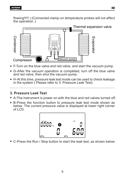
Use Function to enter the pressure test screen only in an approved isolated test. Run/Stop records start pressure, current pressure, difference and elapsed time. Record temperature because it changes pressure. Use only the approved test medium and pressure; never air or oxygen.
Completion check: Medium, pressure, stabilization, duration and acceptance match the service procedure.
Step 13: Treat relative vacuum as a trend
In Vacuum mode, connect the center path to compliant evacuation equipment and follow the specified valve sequence. The LM120’s coarse relative-vacuum reading shows gross progress. Use a dedicated absolute vacuum gauge and required decay test when the procedure specifies micron-level acceptance.
Completion check: Final evacuation is accepted by the required absolute method, not a percentage alone.
Step 14: Isolate, disconnect and store
Return the service equipment and vehicle to the required shutdown state. Close both LM120 valves, manage trapped refrigerant through approved recovery or low-loss equipment, disconnect in the specified order and restore port caps. Wipe the manifold, protect clean fittings and remove batteries for extended storage.
Completion check: No refrigerant was intentionally vented, ports are restored and the result is saved to the correct job.
Reliable LM120 data gates
| Gate | Pass condition | Stop or repeat when |
|---|---|---|
| Identity | Refrigerant and units are verified | Selection is guessed from pressure |
| Setup | Valves closed, hoses traced, open-air zero complete | A channel was zeroed under pressure |
| Condition | Load, ambient, airflow and control state are stable | Values come from changing conditions |
| Decision | Both pressures and temperature evidence match vehicle data | One number drives a charge decision |
Common LM120 problems
A pressure channel will not zero
Disconnect it from all pressure and vacuum sources, check for trapped hose pressure and let the instrument stabilize. Persistent offset requires evaluation rather than mental correction.
A temperature field is blank
Confirm that the exact package includes a compatible probe, seat the connector and inspect the lead. LM120 and LM120+ accessory bundles can differ.
SH or SC looks wrong
Recheck refrigerant selection, probe channel/location, metal contact and system stability. Do not alter charge until the complete vehicle procedure supports it.
A pressure hold changes
Record temperature and check external hoses, couplers and valves. Pressure change indicates a trend, not automatically the system leak location.
AUTOOL LM120 FAQ
How is LM120 different from LM120+?
They share the core manual and operating logic, but current accessory configurations can differ. Confirm hoses and wired temperature clamps on the exact product package rather than assuming the plus bundle is included.
Can LM120 identify refrigerant?
No. You select one of 89 datasets after verifying refrigerant identity.
Can its vacuum percentage replace a micron gauge?
No. Use the absolute vacuum measurement and decay criterion required by the vehicle procedure.
What batteries does LM120 use?
Four 1.5 V AA/LR6 batteries.
The reliable LM120 workflow
Verify refrigerant and service data, inspect and close the manifold, install four AA batteries, select the exact dataset and units, zero both open-air channels, route probes and hoses safely, capture synchronized pressure and temperature data, use timed and vacuum modes only within their limits, then isolate and disconnect without venting. That makes the LM120 a repeatable measurement tool instead of a source of generic pressure guesses.


Comments 0
Questions, fixes, and real-world diagnostic notes from readers.
Be the first to share a diagnostic result or ask a follow-up question.