
How to Use the AUTOOL HTS705 Dry Ice Blasting Machine

Use the AUTOOL HTS705 only after the workpiece is de-energized, the surface has passed a small-area compatibility test, and the workshop has an engineered way to prevent carbon-dioxide buildup. Dry ice leaves no solid blasting media behind, but it still creates cold CO₂ gas, noise, high-velocity debris, and removed contamination that must be controlled.
The reliable HTS705 sequence is to verify dry, high-flow compressed air, connect the correct hose and nozzle, test with the ice-feed control at zero, load fresh 3 mm pellets, prove the settings on a sacrificial or inconspicuous area, clean in controlled passes, then return the feed to zero and purge the hose before every pause or shutdown.
Updated August 27, 2026.
In this guide
- Decide whether dry ice blasting suits the surface
- Control CO₂, cold, noise, and flying debris first
- Before you start
- Understand the HTS705 controls and flow path
- HTS705 step-by-step operating procedure
- How to judge the result
- Common HTS705 mistakes
- HTS705 maintenance after the job
- Frequently asked questions
- The reliable HTS705 workflow
Decide whether dry ice blasting suits the surface
The AUTOOL HTS705 accelerates dry-ice pellets with an external compressed-air source. Impact, rapid cooling, and sublimation help break the bond between a contaminant and a suitable substrate. The dry ice changes to CO₂ gas, so there is no spent walnut, sand, or glass media to collect; the detached carbon, grease, paint, corrosion, and dirt still remain and may become airborne.
HTS705 can be useful on compatible engine parts, exposed intake ports, throttle bodies, wheels, underbody parts, fixtures, and workshop surfaces. Compatibility depends on the substrate, coating, seal, adhesive, finish, temperature, contamination, nozzle, distance, angle, air delivery, ice quality, and cleaning goal. It is not automatically safe for soft trim, brittle plastic, wiring, connectors, sensors, bearing seals, plated finishes, thin paint, glass, hot components, or any assembled path where loosened debris could enter a cylinder, oil passage, intake, bearing, or electrical enclosure.
Start with the job specification. Identify what must be removed, what must remain, the acceptable surface condition, and how released contamination will be captured. De-energize moving equipment. For vehicle work, obtain the procedure for access, component protection, valve position, debris control, reassembly, torque, and post-service checks.
Control CO₂, cold, noise, and flying debris first
Dry ice is solid CO₂ at about −78.5°C. Direct contact can cause frostbite, and the pellets and blast stream can injure eyes and skin. As the pellets warm and strike the surface, they release colorless, odorless CO₂ gas. You cannot rely on smell to detect a dangerous accumulation, and an open door alone does not prove that the operator’s breathing zone is safe.
Do not blast or store dry ice in a vehicle cabin, pit, cellar, tank, small room, or other confined or poorly ventilated space. Provide mechanical fresh-air ventilation and extraction sized for the amount of dry ice used and the actual room geometry. Because CO₂ is heavier than air, include low areas and pits in the assessment. Use a calibrated direct-reading CO₂ monitor with audible and visual alarms where the risk assessment requires it; place the sensor where the site plan says it can detect accumulation, not merely beside an open doorway.
For U.S. workplace context, NIOSH lists 5,000 ppm as an 8-hour recommended exposure limit, 30,000 ppm as a short-term limit, and 40,000 ppm as immediately dangerous to life and health. Apply the exposure limits and alarm strategy required in your jurisdiction. Never enter an alarmed, oxygen-deficient, unknown, or potentially IDLH atmosphere to retrieve a tool or help a person without the site’s trained emergency response and proper supplied-air equipment.
Wear insulated dry-ice gloves when loading pellets; safety goggles plus a face shield where the debris assessment requires it; hearing protection selected from measured noise; protective clothing; and closed-toe safety footwear. Choose respiratory protection from the contaminant assessment. A dust respirator does not supply oxygen and does not make a CO₂-rich space safe.
Stop: Leave the area and follow the emergency plan for a CO₂ alarm, headache, dizziness, unusual breathlessness, confusion, loss of coordination, or another possible exposure symptom. Do not continue by adding a mask or opening one window.
Before you start
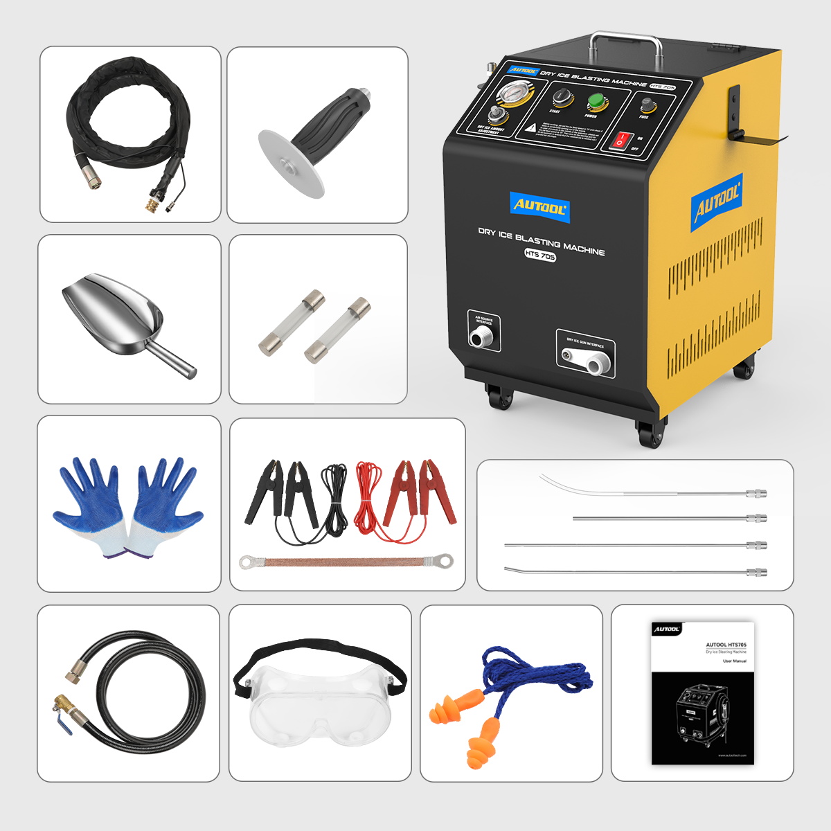
Use the AUTOOL manual download center to obtain the manual that matches the delivered machine. Check the HTS705 nameplate, regional voltage, electrical ground, maximum pressure, air-flow requirement, hose rating, nozzle, and received accessories.
Prepare:
- fresh, clean, unopened 3 mm dry-ice pellets close to the time of use;
- a dry, oil-free, filtered external compressed-air source with adequate tank, duty cycle, hose bore, couplers, and delivered flow;
- the HTS705 ice hose with signal line, spray handle, selected 5 or 6 mm nozzle where supplied for the exact configuration, and correctly rated air hose;
- barriers, warning signs, ventilation, CO₂ monitoring where required, debris screens, extraction or collection equipment, and safe waste containers;
- insulated gloves, eye and face protection, hearing protection, protective clothing, safety footwear, and task-specific respiratory protection;
- masking plugs, protective covers, strong lighting, inspection tools, and a sacrificial coupon or inconspicuous test area.
The exact HTS705 manual lists a 5 kg dry-ice capacity, 3 mm pellets, 0–3.2 kg/min adjustable feed, an air-supply range of 0.3–1.0 MPa, and more than 1–3 m³/min airflow. Its cautions and troubleshooting section call for a supply above or not less than 6 bar and at least 1 m³/min, with an air line larger than DN20 recommended to reduce pressure drop. Confirm the delivered revision and measure behavior under flow at the machine. Never exceed the lowest rating of the machine, hose, fitting, nozzle, workpiece, or site system.
Place the machine upright on a stable, dry floor and secure its casters. Keep the power lead out of wet areas and away from heat, oil, sharp edges, the blast stream, and traffic. Inspect the power cord, protective ground, fuse, switches, gauge, feed controller, tank and lid, air inlet, hose outlet, signal connector, ice hose, handle, trigger, nozzle, seals, couplers, and wheels.
Stop: Do not operate with damaged electrical insulation, missing ground, a leaking or thinned ice hose, loose fitting, blocked nozzle, contaminated hopper, oily or wet air, unstable compressor, defeated ventilation, active CO₂ alarm, unknown substrate, or people inside the exclusion zone.
Understand the HTS705 controls and flow path
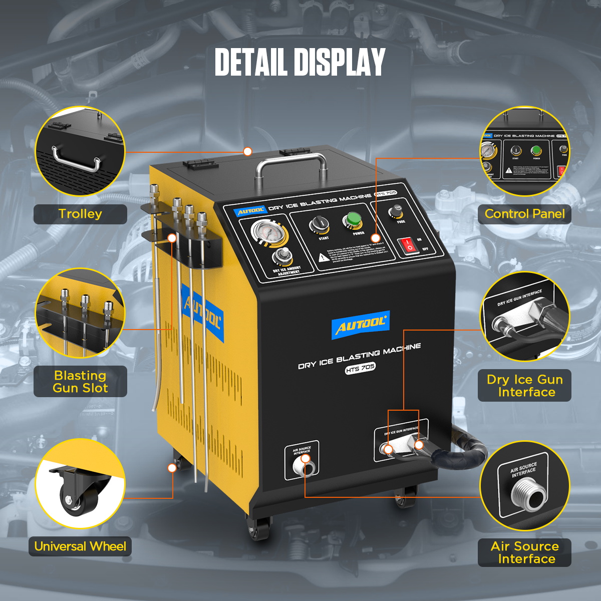
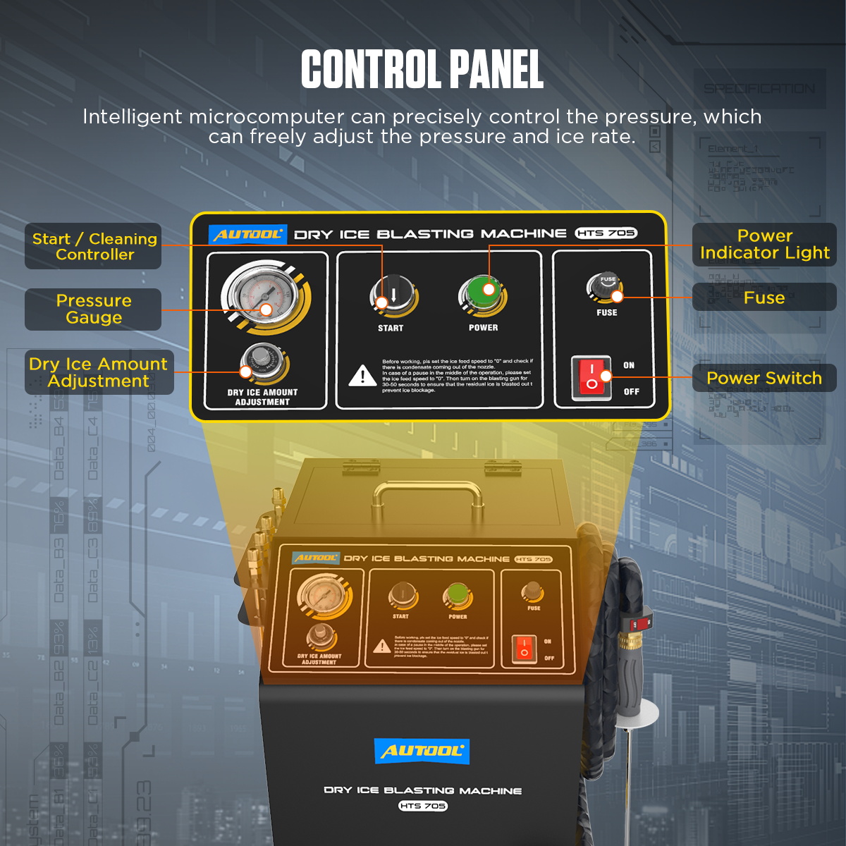
Locate the pressure gauge, dry-ice amount controller, green Start control, green Power indicator, fuse, main power switch, dry-ice tank, external-air inlet, dry-ice outlet, signal interface, hose bracket, and casters. The external compressor provides the blast energy. The machine meters pellets into that airflow, and the handle switch starts the delivery sequence.
Trace the system before pressurizing: compressor and air treatment to the machine air inlet; machine outlet and signal connection to the ice hose; hose to spray handle; selected nozzle to the work area. Support the hose so it does not pull on a fitting, cross a walkway, touch a hot component, or kink around a sharp corner.
The ice-feed controller changes pellet delivery, not just air pressure. At zero, the gun can clear moisture and remaining ice from the hose. This zero-feed purge is a required operating step before loading, during pauses, and before shutdown.
HTS705 step-by-step operating procedure
Step 1: Define the target, substrate, and acceptance test
Document the contaminant and the surface beneath it. Determine whether the desired result is loose-carbon removal, degreasing, coating removal, wheel cleaning, intake-valve cleaning, or another approved task. Record the baseline with comparable photos and note fragile coatings, labels, seals, electrical parts, openings, cracks, corrosion, and existing damage.
Decide what constitutes a pass before blasting. “Looks cleaner” is not enough when a coating thickness, surface roughness, electrical function, sealing face, valve condition, or dimensional tolerance matters.
Completion check: The approved surface, protected features, debris-control method, test area, and final inspection are documented.
Step 2: Establish the ventilation and exclusion zone
Start and verify the required fresh-air and extraction system. Test the CO₂ monitor and alarms according to its instructions, then place it according to the site risk assessment. Prevent gas from collecting in pits, drains, under a vehicle, or behind temporary curtains. Keep dry-ice storage ventilated and never place pellets in a sealed container.
Set barriers for the blast direction, ricochet zone, hose route, and operator movement. Remove bystanders and protect adjacent vehicles, glass, paint, electronics, air intakes, and food-contact areas from loosened debris.
Pass condition: Ventilation is running, monitoring and alarms are ready where required, the escape route is open, and no unprotected person can enter the blast or gas-accumulation zone.
Step 3: Prepare and de-energize the workpiece
Switch off and isolate any moving, electrical, thermal, pneumatic, hydraulic, fuel, or ignition energy required by the equipment or vehicle procedure. Let hot surfaces reach an approved temperature. Remove access parts only as instructed, then cover every opening not being cleaned.
For an exposed intake port, prove the target intake valve fully closed and protect neighboring ports. Dry ice sublimates, but loosened carbon and other debris do not. Do not blast into an open valve or depend on the engine to ingest the released material safely.
Clean loose grit by an approved method before dry-ice blasting. A hard particle caught in the jet can become an unintended abrasive projectile.
Completion check: Energy is isolated, the target is stable and accessible, and every unintended path and vulnerable component is protected.
Step 4: Connect the hose, handle, nozzle, air, and power
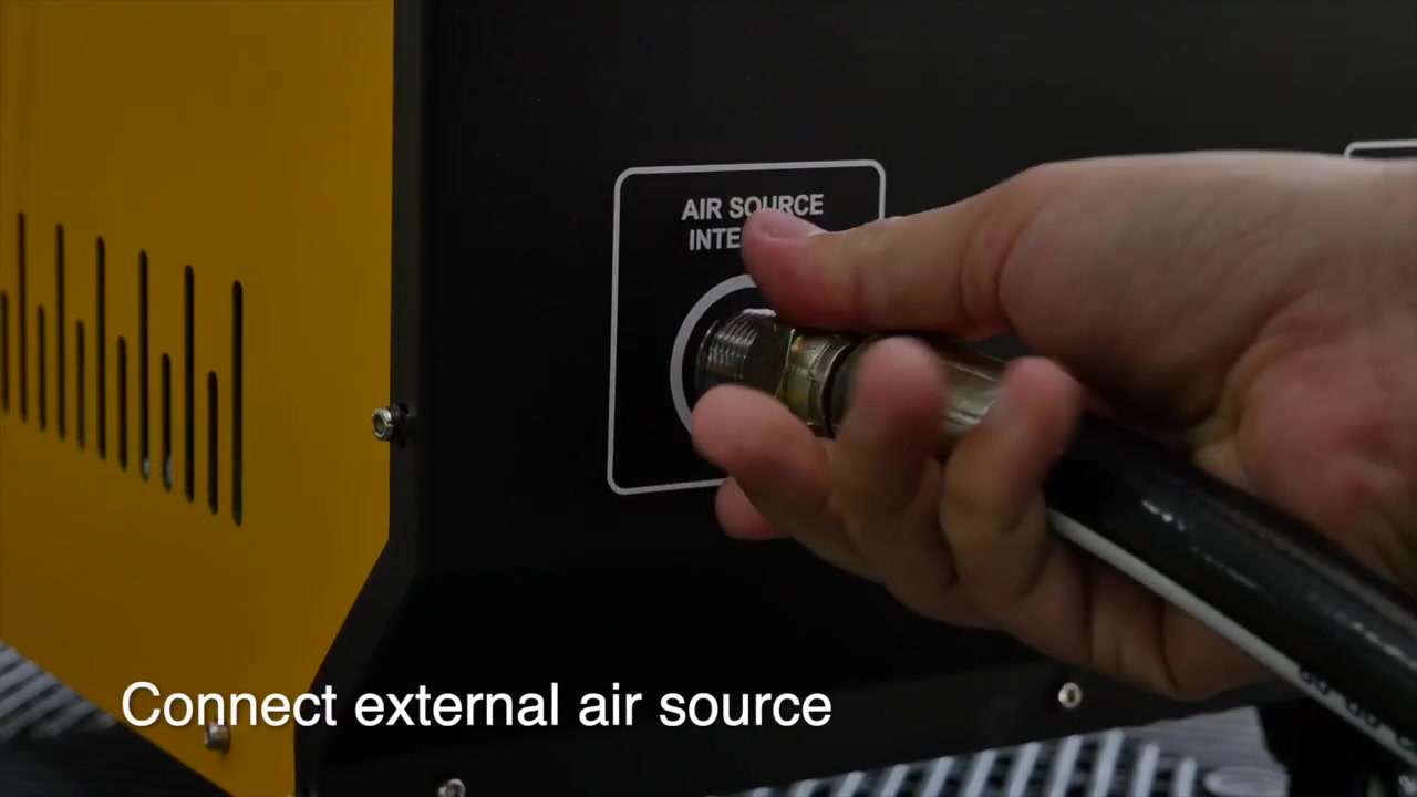
With the main switch off, power disconnected, the compressor isolated, and the system depressurized, attach the ice hose and signal connection to the marked machine interfaces. Fit the selected nozzle squarely to the spray handle and secure it with the correct fitting. Inspect the full hose length and keep the nozzle pointed into a safe test enclosure.
Connect a correctly rated, large-bore air line to the external-air inlet. Avoid unnecessary reducers, restrictive quick couplers, excessive hose length, and sharp bends. Connect grounded power only after every air and blast connection is secure.
Common mistake: Choosing pressure by the compressor tank gauge. Pressure and flow can fall sharply through a thin, long, wet, or restrictive supply line. Verify delivery at the machine while air is flowing.
Completion check: The nozzle, hose, signal, air, and grounded power connections are secure, rated, supported, and free of leaks or kinks.
Step 5: Perform the zero-feed air test
Keep the hopper empty and set the dry-ice amount controller to 0. Turn on power, select the machine’s operating or Start state, then press the handle switch while the nozzle points into the safe test enclosure. Confirm the gauge, air delivery, trigger response, signal connection, hose behavior, and machine sound.
Run the air-only test for 30–50 seconds or until no condensed water is expelled, as the manual directs. Moisture or oil can cause ice blockage and can contaminate the surface. If liquid continues, stop and service the compressor, dryer, filters, drain, hose, and air treatment; do not hide the problem by loading pellets.
Pass condition: Airflow is stable and dry, no leak or abnormal vibration is present, and the feed controller remains at 0.
Step 6: Load fresh 3 mm dry ice safely
Release the handle, isolate the blast function as the manual directs, and put on insulated gloves and eye protection. Open the hopper only in the ventilated loading area. Use a clean scoop to add fresh 3 mm pellets without exceeding the 5 kg machine capacity. Keep packaging, water, tools, hands, and foreign objects out of the feed mechanism.
Close and secure the lid immediately. Dry ice continuously sublimates, so load only what the planned task can use and do not leave pellets in the machine for storage. Never seal leftover dry ice in an airtight container.
Completion check: Clean 3 mm pellets are loaded within the 5 kg capacity, the hopper is free of foreign material, and the lid is closed.
Step 7: Set an initial feed and prove it on a test area
With the nozzle inside the controlled test zone, establish the required air delivery, then introduce dry ice gradually. The manual suggests an initial feed setting around 5 for the normal barrel or around 3 for a smaller-inner-diameter barrel, followed by adjustment to the result. Treat those dial positions as machine starting references, not universal surface settings.
Begin on a sacrificial coupon or inconspicuous area at the lowest effective combination of feed, pressure, distance, angle, and dwell permitted by the exact procedure. Keep the nozzle moving. Stop and inspect for coating lift, embrittlement, cracking, discoloration, texture change, seal damage, condensation, or debris behavior.
Pass condition: The contaminant releases at a controlled rate while the intended substrate and protected features remain unchanged.
Step 8: Clean in overlapping controlled passes
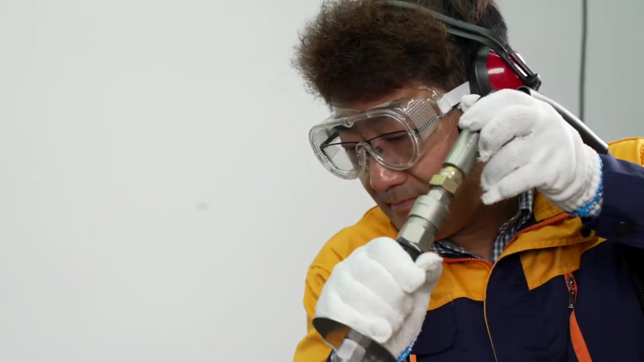
Hold the spray handle with stable footing and two-hand control. Aim only at the approved surface, begin moving before dwelling, and use overlapping passes. Adjust one variable at a time—distance, angle, traverse speed, feed, then air within the allowed range—so the result remains explainable.
Work from a direction that sends released debris toward the capture zone and away from the operator, openings, bearings, seals, electrical connectors, and finished surfaces. Keep the hose behind the operator and never wrap it around the body. Do not touch the nozzle or metal barrel during operation.
Stop: Release the trigger for loss of control, damaged protection, ricochet, escaping debris, abnormal noise, hose movement, falling pressure, condensation, surface change, ventilation failure, CO₂ alarm, exposure symptom, or any person entering the exclusion zone.
Completion check: The target area meets the approved condition without visible substrate or adjacent-component damage, and debris remains controlled.
Step 9: Use engine and intake applications conservatively
For engine-bay work, protect alternators, exposed connectors, sensors, open breathers, intake ducts, thin labels, insulation, fragile plastic, paint edges, and rotating seals. Clean only a de-energized, suitably cooled assembly. Do not direct debris into the alternator, belt path, air intake, drain, or cabin ventilation inlet.
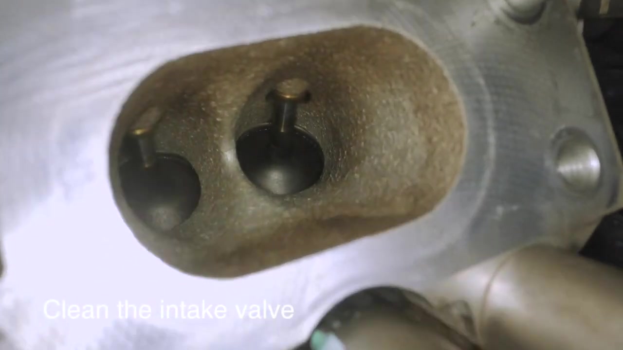
For an exposed intake port, keep the exact target valve closed, protect the other runners, and extract loosened carbon continuously. Use short passes and a borescope or direct light between them. The absence of solid dry ice after sublimation does not prove that carbon fragments have been removed.
For wheels and underbody parts, identify sensitive finishes, tire valves, sensors, rubber, brake friction surfaces, boots, seals, and loose corrosion. Dry-ice blasting can lift weak paint or loosely bonded material; it does not restore deep corrosion or prove a component serviceable.
Completion check: The exact application-specific protection and debris inspection pass before the nozzle moves to another area.
Step 10: Inspect and remove released contamination
Set feed to 0 and continue air through the nozzle while directing loose debris toward the approved extraction or collection area. Then release the trigger and inspect under strong light. Use a borescope for recesses and engine openings. Collect detached carbon, coating, grease, rust, and other contamination according to its hazards and local rules.
Compare the result with the baseline and acceptance criterion. Inspect coatings, edges, seals, wiring, threads, gasket faces, bearings, sensors, valve areas, and surrounding openings. A clean photograph does not prove mechanical, electrical, or sealing performance.
Pass condition: The required contamination is removed, no harmful surface change is visible, and all released debris is accounted for before reassembly or energization.
Step 11: Purge before every pause
Before a pause or change of position, turn the dry-ice amount controller to 0, then keep the spray handle running for 30–50 seconds so residual pellets leave the feed pipe. Do this even when the next pass is planned shortly. Stopping with pellets in the hose lets sublimating dry ice and moist compressed air create an internal blockage.
If the hose is already air-flowing but not feeding ice, stop normal cleaning. Follow the exact troubleshooting sequence away from the workpiece: verify dry, oil-free air, check fill level and hopper condition, inspect for wear or restriction, set feed to 0, and use the manual’s longer clearing run only with the nozzle secured in the safe enclosure. Do not look into, strike, heat, or dismantle a pressurized hose.
Completion check: The feed is at 0 and the hose is visibly clear before the trigger is released for a pause.
Step 12: Shut down, depressurize, and store
At the end of the job, return feed to 0 and run the 30–50 second clearing purge until no pellet or moisture exits. Release the trigger, turn off machine power, close the compressor outlet, safely bleed trapped pressure, verify the gauge and hose are depressurized, unplug power, then disconnect the air supply.
Remove remaining dry ice only by the approved method while wearing insulated protection and maintaining ventilation. Allow it to sublimate in a designated open, secure, ventilated area—never in a sealed container, drain, vehicle, room, or public walkway. Clean the hopper and machine without adding water to electrical or feed components.
Inspect the hose, nozzle, fittings, signal line, tank, lid, cable, switches, gauge, wheels, and filters. Store HTS705 clean, dry, unplugged, depressurized, and protected from heat, moisture, corrosion, and unauthorized use.
Completion check: No dry ice remains trapped in the hose, all energy is isolated, leftover pellets are controlled, released waste is managed, and the dry machine is ready for inspection before its next job.
How to judge the result
Use five gates:
- Surface gate: the specified contaminant is removed without unacceptable coating, finish, seal, thread, plastic, wiring, bearing, or substrate change.
- Debris gate: detached contamination is collected and has not entered an engine opening, electrical enclosure, bearing, intake, drain, or adjacent work area.
- Atmosphere gate: ventilation remained effective, required monitoring stayed within the site limits, and no exposure symptom or alarm occurred.
- Machine gate: feed and airflow were stable, no moisture or leak appeared, and the hose was purged before every pause and shutdown.
- Functional gate: reassembly, leak, scan, electrical, mechanical, and other specified checks pass after energy is restored.
Dry ice removes a cleaning medium from the waste stream, not the original dirt. Keep the cleanup and exposure plan matched to whatever the blast releases.
Common HTS705 mistakes
Treating a large workshop as automatically ventilated
Room volume does not prove safe CO₂ concentration. Assess dry-ice consumption, air movement, low points, partitions, vehicle position, extraction, monitor placement, and occupied time.
Using wet compressed air
Water and oil promote clumping, blockages, unstable feed, and surface contamination. Complete the zero-feed purge and correct air treatment before pellets are loaded.
Copying a pressure or dial setting from a video
The correct combination depends on the delivered machine, air system, nozzle, pellet quality, surface, coating, distance, and desired result. Test and adjust one variable at a time.
Assuming sublimation eliminates all cleanup
The dry ice becomes gas, but carbon, grease, paint, rust, and other contamination remain. Capture and dispose of the released material appropriately.
Stopping without clearing the hose
Return feed to 0 and run air for 30–50 seconds before every pause. This is the primary operating control for residual-ice blockage.
Using dry ice as permission to blast delicate parts
Cold shock, impact, debris, and compressed air can damage finishes, seals, plastic, labels, electronics, and bearings. Perform a controlled compatibility test first.
HTS705 maintenance after the job
After power and pressure are isolated:
- drain and service the upstream compressor and air-treatment system;
- inspect the ice hose for thinning, cracking, abrasion, cold damage, leaks, and damaged signal wiring;
- inspect the nozzle, handle, trigger, fittings, seals, inlet, outlet, hopper, feed mechanism, lid, gauge, cable, fuse, and casters;
- remove dry loose contamination without introducing water, oil, or foreign objects into the feed path;
- tighten only the user-serviceable connections specified in the manual;
- have electrical, pressure, signal, feed, or worn-hose faults repaired by qualified service.
Never tape a leaking blast hose, bypass a ground, enlarge a nozzle, defeat a lid, or use heat or tools to clear a pressurized blockage.
Frequently asked questions
Does HTS705 include an air compressor?
No. It requires an external dry, oil-free, filtered compressed-air source with enough pressure, delivered flow, tank capacity, hose bore, and duty cycle for the task.
What size dry ice should I use?
The exact HTS705 manual specifies 3 mm pellets. Product materials mentioning other sizes do not override the manual and machine supplied with your unit.
How much dry ice can HTS705 hold?
The exact manual and current product page specify a 5 kg capacity. Load only enough fresh pellets for the planned job and never store dry ice in the machine.
What pressure and airflow are required?
The manual lists 0.3–1.0 MPa and more than 1–3 m³/min, while its operating cautions and troubleshooting call for at least 6 bar and at least 1 m³/min with a suitably large supply pipe. Confirm the delivered revision and verify performance under flow without exceeding the lowest component or surface limit.
Why must I start with the feed at zero?
Zero feed lets you test air, controls, moisture, hose behavior, and the work zone without pellets. It is also the clearing state used before pauses and shutdown.
How long should I purge the hose?
The manual specifies 30–50 seconds at feed 0 before a pause or final shutdown. Continue until no pellet or moisture exits; use the longer troubleshooting process only for an actual blockage and only in a secured safe enclosure.
Does dry ice blasting leave no residue?
It leaves no solid dry-ice blasting media because the pellets sublimate. Removed carbon, grease, coating, corrosion, dust, and other contamination still require capture and disposal.
Can I use HTS705 inside a vehicle?
Do not use it in a cabin or another confined or poorly ventilated space. CO₂ can accumulate without a warning smell. Use an engineered, risk-assessed work area with ventilation and monitoring as required.
Can HTS705 clean intake valves?
It can clean a suitably exposed intake port when the vehicle procedure allows it, the target valve is fully closed, neighboring openings are protected, and released carbon is extracted and inspected. Dry-ice sublimation does not remove carbon fragments for you.
Can I clean electronics while they are energized?
No. De-energize and isolate the equipment as required, assess condensation and component sensitivity, protect openings and connectors, and prove the method on a safe test area.
What should I do if a CO₂ alarm activates?
Stop work, leave by the established route, prevent entry, and follow the site’s emergency plan. Do not re-enter simply because the machine is off; the atmosphere must be made and verified safe by the approved procedure.
The reliable HTS705 workflow
The dependable sequence is: assess the surface and released contamination, engineer ventilation and monitoring, isolate energy, connect a dry high-flow air path, test at zero feed, load fresh 3 mm pellets, prove the settings on a test area, clean in controlled passes, capture the debris, purge at zero before every pause, then depressurize and store the machine dry. HTS705 removes the blasting media by sublimation; professional control is still required for the gas, cold, noise, jet, surface, and waste it leaves behind.






Comments 0
Questions, fixes, and real-world diagnostic notes from readers.
Be the first to share a diagnostic result or ask a follow-up question.