
How to Use the AUTOOL CT160 Fuel Injector Cleaner and Tester

Use the AUTOOL CT160 as a controlled before-and-after comparison bench: keep every injector tied to its original cylinder, clean the set under one documented ultrasonic process, then repeat the same leakage, spray-pattern, and flow tests with the same installation, test fluid, pressure, pulse settings, mode, and duration. The repeatable comparison—not heat or one cylinder reading by itself—is the useful result.
The CT160 services up to four compatible standard 12 V gasoline injectors and adds heated ultrasonic cleaning to the four-position format. The current model information specifies heating up to 45°C. That is a machine ceiling, not a required setting for every injector or liquid: stay within the lowest limit given by the delivered CT160 instructions, the cleaning-liquid label and safety data sheet, and the injector material guidance. CT160 can ultrasonically clean some diesel injectors, but it cannot test them, and it is not a GDI high-pressure injector bench.
Last reviewed: August 27, 2026.
In this guide
- The safe CT160 workflow at a glance
- What the CT160 can—and cannot—prove
- Before you fill either CT160 circuit
- Know the controls you will use
- Step-by-step: heated ultrasonic cleaning
- Step-by-step: mount and test the injectors
- Interpret the result without overdiagnosing
- Shut down, drain, and store the CT160
- CT160 troubleshooting boundaries
- Frequently asked questions
- Control the process, then trust the comparison
The safe CT160 workflow at a glance
Use this order:
- Confirm the exact CT160, input voltage, injector type, adapters, seals, and liquid requirements.
- Relieve vehicle fuel pressure and remove the injectors under the vehicle maker’s procedure.
- Label every injector by cylinder, inspect it, and record a safe baseline when possible.
- Add approved ultrasonic cleaning liquid, keep electrical connectors above the liquid, and connect the correct pulse leads.
- Run ultrasonic cleaning; use the heating switch only with a filled bath and within the lowest applicable temperature limit.
- Stop cleaning, switch heat off, and recover or handle the cleaning liquid as its instructions require.
- Mount the injectors squarely on the test rail and plug every unused position.
- Add dedicated injector test fluid to the test circuit—not the ultrasonic bath liquid.
- Run leakage, spray-pattern, and volume comparisons at injector-specific settings.
- Repeat the same settings after cleaning, record the result, then depressurize, drain, and store the machine.
Stop for an external fluid leak, a crooked injector, a rail that will not clamp evenly, a damaged measuring cylinder, unstable pressure, liquid at an electrical connection, or abnormal heat, odor, smoke, sound, or control response.
What the CT160 can—and cannot—prove
The four glass cylinders let you observe a matched set side by side. You can identify visible nozzle dripping, a distorted or intermittent spray pattern, a restricted injector, or a relative flow imbalance under the selected conditions. Repeating a result after cleaning helps show whether deposits contributed to the difference.
The bench cannot identify every cause of a vehicle symptom. If all injectors appear weak, first verify the test-fluid level, pressure, mode, pulse settings, electrical leads, adapters, seals, plugs, and rail installation. On the vehicle, supply pressure, pump volume, wiring, driver control, ignition, intake leakage, compression, and mechanical condition can create similar symptoms.
Heating does not diagnose an injector. It only changes the ultrasonic cleaning process. A hotter or longer cycle is not automatically better, and a reading taken under different test conditions is not a valid before-and-after comparison.
Before you fill either CT160 circuit
Confirm the exact machine and injector type
Read the nameplate and delivered instructions. Confirm the machine voltage and plug version, then verify that every injector is a compatible standard gasoline type and that the correct upper and lower adapters are available. Do not put a GDI high-pressure injector on this bench. If a diesel injector enters the ultrasonic tank, treat that as cleaning only; do not connect it to the CT160 test circuit.
The current AUTOOL CT160 page can help you identify the heated four-position configuration. The delivered unit, serial-specific instructions, injector data, liquid instructions, and vehicle service information make the final compatibility decision.
Prepare the bench and protect the work area
Place the CT160 on a stable, level bench in a well-ventilated area. Keep flames, sparks, hot work, smoking, and other ignition sources away from fuel and service liquids. Wear eye protection and fluid-resistant gloves selected from the liquid safety data sheet. Keep compatible absorbent material and correctly labeled recovery containers within reach.
The measuring cylinders are glass. Do not run the machine with a chipped, cracked, or loose cylinder, and never lean over the rail while the circuit is pressurized. Inspect the power cord, plug, switches, hoses, gauge, leads, drain valves, rail, and visible seals before use.
Keep cleaning liquid and test fluid separate
CT160 has two liquid jobs:
- Ultrasonic cleaning liquid belongs in the open stainless cleaning tank. Use a dedicated product approved for ultrasonic injector cleaning and compatible with the injector body, coatings, plastics, filter, seals, and tank.
- Injector test fluid belongs in the machine’s pressurized test circuit. It is used for leakage, spray, and measuring-cylinder comparisons.
Do not substitute gasoline, kerosene, ultrasonic cleaning liquid, or an unapproved flammable or corrosive liquid in the test circuit. Do not mix recovered liquids, and never switch on ultrasonic cleaning or heating with an empty bath.
Preserve identity and record the baseline
Label the injectors by original cylinder before they can be mixed. A reliable record includes injector position, test fluid, pressure, selected function, pulse width when adjustable, duration or injection count, leakage result, spray description, and settled cylinder reading.
Test before cleaning when the injector condition and setup allow it safely. If heavy exterior contamination or damaged seals make a baseline unsafe, document why and begin with inspection and cleaning. Never force a “before” run merely to complete a table.
Know the controls you will use
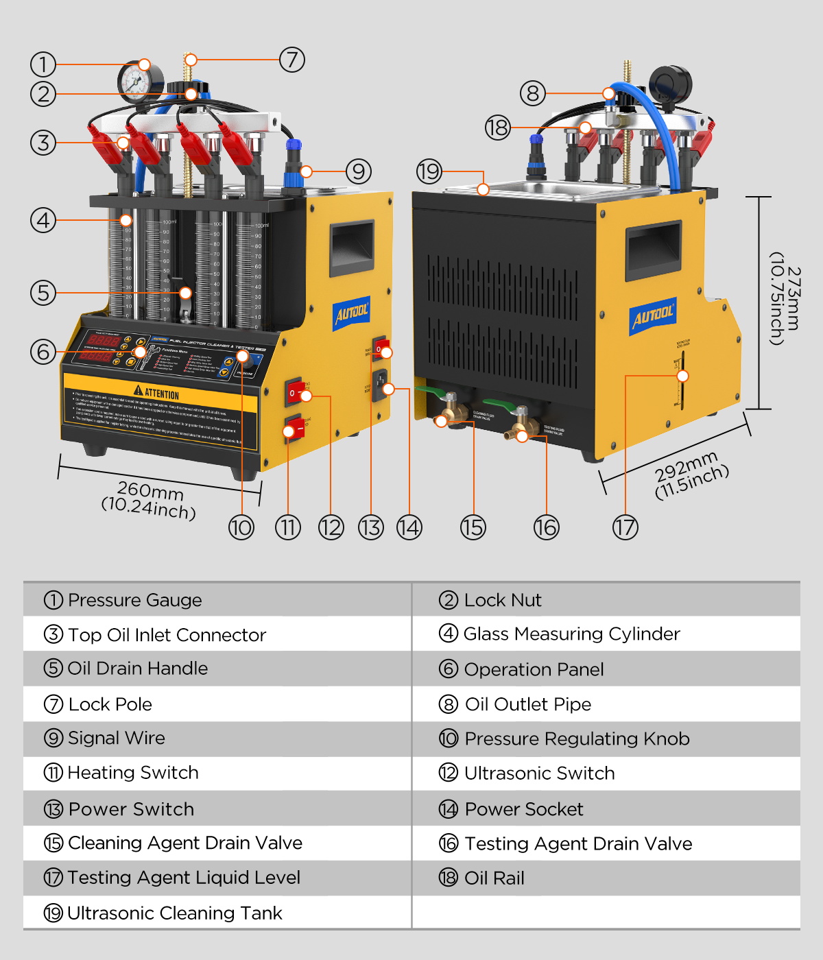
Locate the ultrasonic tank, cleaning-liquid drain, test-fluid filler and level window, test-fluid drain, four cylinders, injector rail, locking hardware, signal leads, pressure gauge, pressure control, function selector, pulse-width controls, time or injection-count controls, and START, PAUSE, and STOP keys. On the side of the machine, identify the main power, ultrasonic, and heating switches.
Use the labels on the delivered CT160. Some translated diagrams call the test-fluid circuit “oil”; that does not mean engine oil. Fill it only with approved injector test fluid. Do not infer hidden plumbing or valve position from a photograph.
Step-by-step: heated ultrasonic cleaning
Step 1: Remove and identify the injectors
Relieve vehicle fuel pressure, isolate power, and remove the fuel rail and injectors exactly as the vehicle maker specifies. Protect open fuel lines from dirt and ignition sources. Label each injector with its original cylinder before separating it from the rail.
Completion check: Every injector has a durable position label, vehicle openings are capped or protected, and spilled fuel has been controlled.
Common mistake: Mixing the injectors after removal. If cylinder identity is lost, a later improvement or persistent fault cannot be tied reliably to the vehicle symptom.
Step 2: Inspect the injector body and seals
Remove loose exterior dirt before placing an injector in the bath. Inspect the electrical connector, body, inlet screen, outlet or nozzle area, sealing lands, and O-rings. Replace an incorrect, cut, hardened, swollen, flattened, or missing seal with the specified part before any pressure test.
Do not continue with a cracked body, loose terminal, seriously corroded component, damaged sealing land, or an adapter that does not match the injector.
Completion check: The exterior will not contaminate the bath, and every pressure interface is serviceable.
Step 3: Load the ultrasonic bath correctly
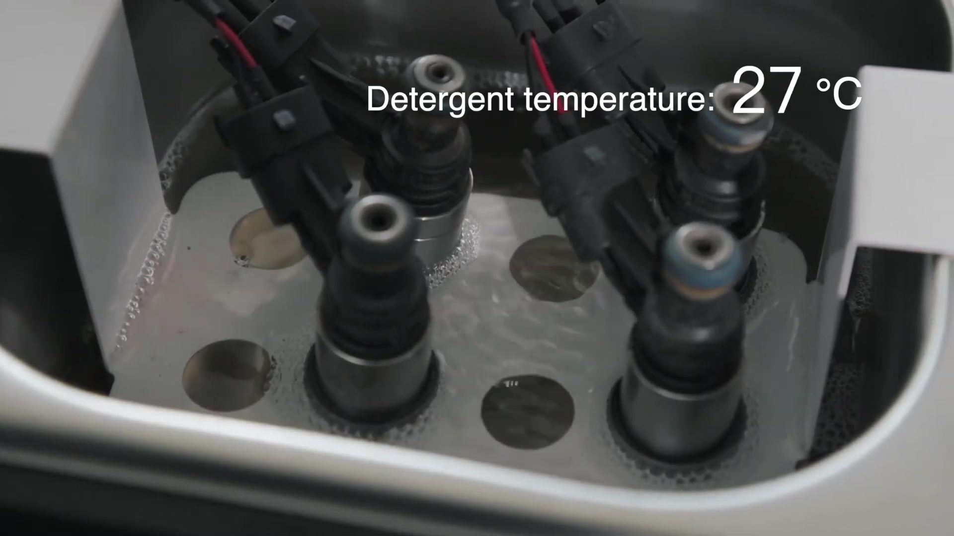
Place the cleaning rack in the tank. Position the injectors so the areas being cleaned contact the approved liquid while electrical connectors and pulse-lead junctions stay above it. Attach the correct CT160 drive leads without stretching wires, crossing bare clips, or loading the injector sideways.
Add the approved ultrasonic cleaning liquid before activating ultrasound or heat. Use the delivered level guidance and prevent overflow; do not copy a generic volume when the tank and reservoir figures in available documents refer to different circuits or revisions.
Completion check: The injectors are stable, connectors are dry, leads are secure, and the filled bath remains below every electrical connection.
Stop: Do not start an empty bath or continue if liquid can reach a damaged lead, switch, socket, or power inlet.
Step 4: Choose a safe heating boundary
Start with the temperature requirements on the cleaning-liquid label and safety data sheet, then check the injector maker’s material limits and the delivered CT160 instructions. Use the lowest applicable limit. The current CT160 model information states heating up to 45°C, but that does not override a lower liquid or component limit.
Do not assume the function/time display is a temperature display unless the delivered labeling explicitly says so. Do not add an immersion heater or improvise a probe that could damage the tank, touch live parts, contaminate the liquid, or interfere with the injectors.
Completion check: The permitted temperature range and cycle duration are known before the heating switch is used.
Step 5: Run the ultrasonic and heating cycle
Select the CT160 ultrasonic-cleaning function and set the allowed time. Start the injector pulse function and ultrasound according to the delivered control sequence. Enable the separate heating switch only after confirming that the bath is filled, the liquid permits heating, and the injector materials are compatible.
Watch the entire cycle. The injector set should stay stable, electrical connections should remain dry, and the machine should run without abnormal noise, odor, smoke, leakage, or unexpected temperature behavior. Use PAUSE or STOP before correcting a position or connection; do not reach into an active bath.
Completion check: The cycle ends normally and remains inside the documented time and temperature boundary.
Common mistake: Extending heat or time to chase a visibly dramatic bath. Overexposure can damage coatings, plastics, filters, seals, and incompatible liquids without improving an injector.
Step 6: End cleaning before moving to the test circuit
Press STOP, switch ultrasonic cleaning and heat off, and allow the set to reach a safe handling state. Disconnect the leads only after the active cycle has stopped. Remove the injectors, let them drain over the bath, and wipe the exterior with a compatible lint-free material.
Recover, filter, store, or dispose of the cleaning liquid according to its condition, label, safety data sheet, and local requirements. Keep it out of the test-fluid filler.
Step-by-step: mount and test the injectors
Step 7: Install the injectors under the rail
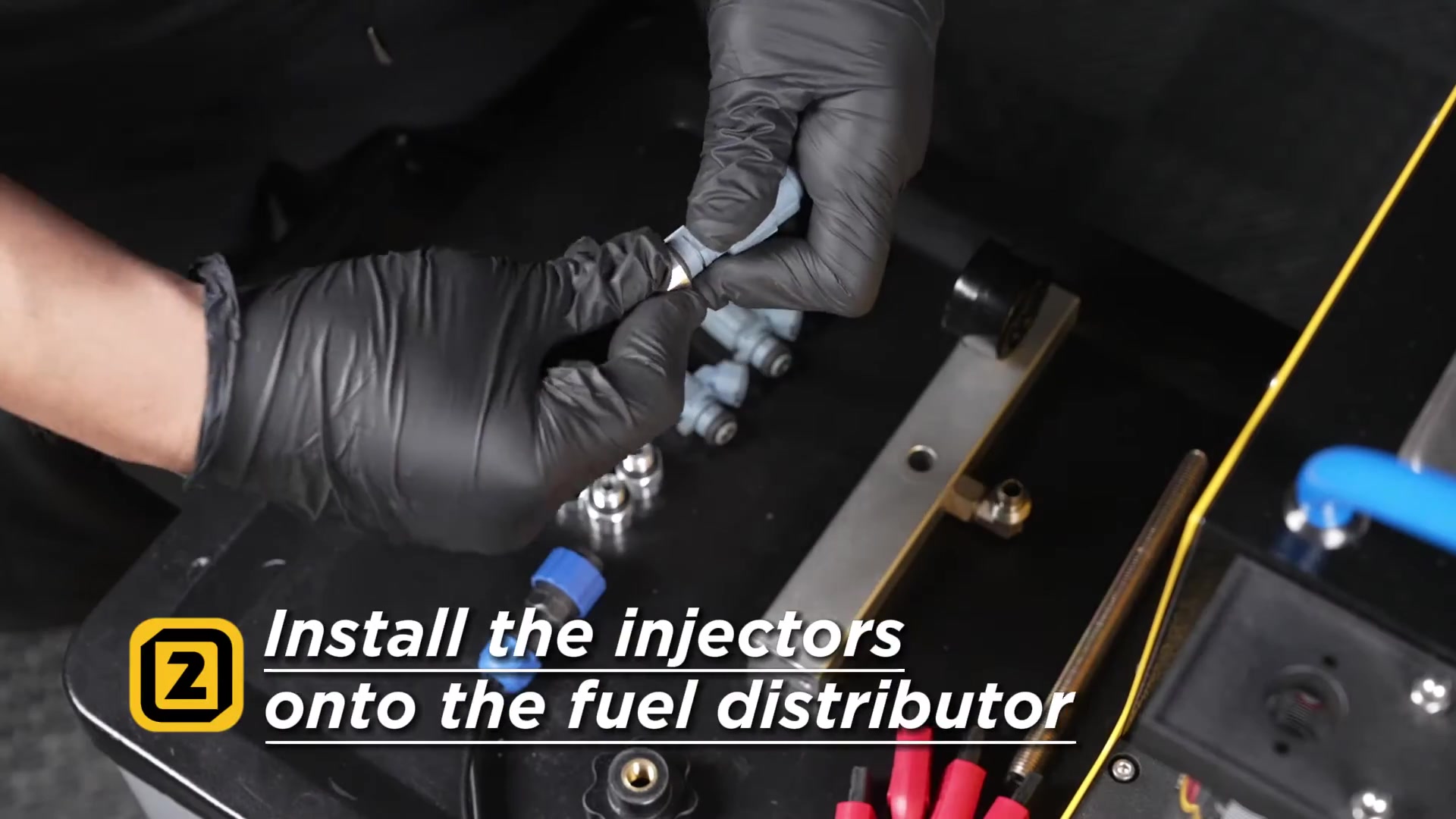
Select the correct adapters for the injector inlet and outlet geometry. Fit serviceable specified O-rings and use only a compatible assembly lubricant when required. Place every injector in its numbered position, seat the upper rail squarely, and tighten the locking hardware evenly. If fewer than four positions are used, install the supplied plugs in every unused outlet.
Connect each signal lead to its matching injector without forcing the connector. The injector should remain vertical and should not carry side load from a hose or wire.
Completion check: The injectors are numbered, square, equally seated, electrically connected, and clamped without a visible seal gap.
Stop: Do not pressurize a crooked injector, damaged seal, loose plug, mismatched adapter, or rail that does not sit parallel.
Step 8: Add dedicated injector test fluid
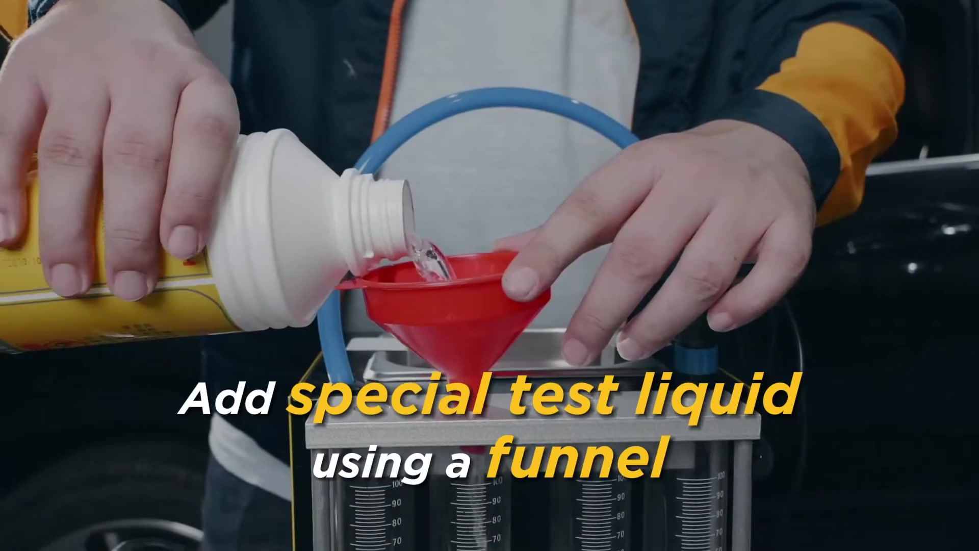
With the machine stopped and the test circuit unpressurized, put only approved injector test fluid into the designated filler. Watch the test-fluid level on the delivered unit, control the pour to prevent overflow, close the filler, and set the test-fluid drain or recycling valve to the specified operating position.
Completion check: Clean test fluid is in the pressurized circuit, spills have not reached electrical parts, and the ultrasonic liquid remains separate.
Step 9: Set one repeatable test condition
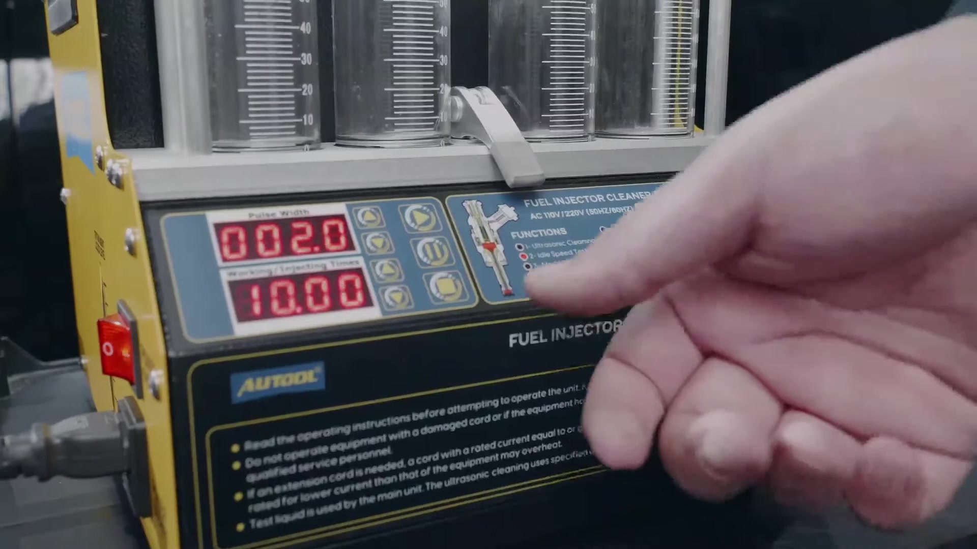
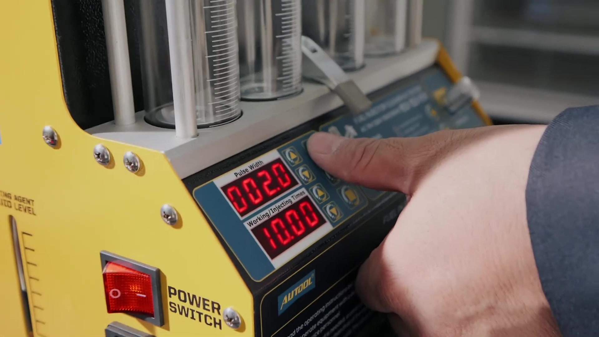
Choose a function suitable for the question you are asking—leakage, a simulated speed mode, or a fixed spray-volume run. Set pressure from current data for the exact injector and remain within the CT160, hose, rail, adapter, and seal limits. Record the function, pressure, pulse width when adjustable, and time or injection count.
Keep those values unchanged for the matched comparison. Change only one variable when you intentionally want to investigate its effect. A generic example pressure is not a universal setting for every standard gasoline injector.
Completion check: The settings are traceable to the injector, and pressure becomes stable without an external leak.
Step 10: Run the leakage check first
Select the leakage function and pressurize the installed set without a normal spray cycle. Watch every nozzle, adapter, O-ring, plug, hose, and rail joint.
A droplet at the injector nozzle can indicate an injector sealing problem. Wetness at an adapter or rail joint is a fixture leak and invalidates the test; it is not evidence that the injector nozzle is faulty.
Completion check: External joints remain dry and every nozzle result is recorded separately.
Stop: Press STOP and release pressure under the delivered instructions if an adapter, plug, hose, rail joint, or injector seal leaks.
Step 11: Compare spray patterns
Select an appropriate idle, medium-speed, high-speed, acceleration, variable-speed, or volume function. Start the run and observe from a safe front and side position without putting your face or hands above the rail. Compare cone shape, direction, atomization, pulse consistency, and shutoff behavior.
Look for a split, deflected, coarse, intermittent, or dribbling pattern. Repeat the same mode if the first view is unclear. Do not compare one injector at one pressure with another injector at a different pressure.
Completion check: Each injector has a recorded pattern under one matched condition.
Step 12: Compare volume and repeat the test
Drain or equalize the cylinders as the delivered procedure requires. Run the chosen volume mode for the same time or injection count, let the liquid settle, and read every cylinder at eye height. Use the injector or vehicle maker’s acceptance limits rather than treating one generic percentage as universal.
Repeat the original baseline settings after cleaning. If one result remains abnormal, swap that injector with another test position and run the same check again. An abnormality that follows the injector supports injector suspicion; an abnormality that stays with one CT160 position points toward a channel, lead, adapter, seal, or setup issue.
Completion check: The before-and-after records use the same conditions and remain tied to the original cylinder identities.
Interpret the result without overdiagnosing
| Observed result | What it can suggest | Best next check |
|---|---|---|
| The set becomes more even after cleaning | Deposits likely contributed to the imbalance | Repeat the matched run once, then reinstall with specified seals and vehicle procedure |
| One injector still drips or remains visibly different | Persistent restriction, wear, contamination, or damage is possible | Swap test positions, repeat the matched test, then refer or replace under injector specifications |
| All injectors show a similar poor result | A common setup or supply error may be influencing the set | Recheck fluid, level, pressure, mode, pulse settings, leads, adapters, filters, plugs, and rail sealing |
| The odd result stays in one CT160 position | The bench channel or fixture may be responsible | Inspect that lead, adapter, seal, plug, hose, and channel before condemning an injector |
| Bench balance is repeatable but the vehicle symptom remains | The root cause may be elsewhere | Test vehicle fuel supply, control signals, wiring, ignition, compression, intake leakage, and mechanical condition |
A small visible difference is not automatically a failed injector. Repeatability, specified limits, measurement resolution, liquid temperature, and identical setup all matter. Record what you observed rather than upgrading a possible cause into a confirmed diagnosis.
Shut down, drain, and store the CT160
Press STOP, return the test circuit to an unpressurized state under the delivered instructions, then switch off heating, ultrasound, main power, and unplug the machine before disconnecting injectors or opening fluid points. Drain the cylinders and test circuit into a labeled test-fluid container. Recover the ultrasonic liquid separately.
Wipe spills with compatible materials. Clean the tank and exposed fittings, inspect adapters and O-rings, and return small parts to labeled storage. Protect the glass cylinders, gauge, rail, cables, switches, and power inlet from impact and contamination.
Do not store the CT160 with pressure trapped in the rail, heat left on, a cracked cylinder, contaminated liquid, a leaking hose, or an unresolved electrical fault.
CT160 troubleshooting boundaries
- The bath does not heat: Confirm approved liquid is present and the correct side heating switch is selected. Stop if the switch, cord, socket, or temperature behavior is abnormal. Do not open the electrical enclosure.
- Ultrasonic cleaning does not operate normally: Verify that the bath is filled and the ultrasonic function and switch are selected. Stop for a dry tank, abnormal sound, smell, smoke, heat, or leakage.
- Pressure will not build: Stop and check test-fluid level, valve position, unused-position plugs, rail seating, adapters, seals, hoses, and visible external leaks. Do not dismantle the pump.
- One cylinder changes on every run: Repeat with matched settings, check for bubbles and leakage, then swap injector positions to separate injector behavior from a channel problem.
- An injector does not pulse: Stop and inspect the connector and approved adapter lead. Swap a known-good CT160 channel only when the delivered procedure allows it; do not improvise direct battery power.
- Liquid reaches an electrical part: Disconnect power only when it is safe, quarantine the machine, and have it inspected before reuse.
Frequently asked questions
What is the main difference between CT150 and CT160?
Both are four-position standard gasoline-injector cleaning and testing benches. CT160 adds a separate ultrasonic-bath heating function; CT150 does not heat its bath.
Must I heat every injector to 45°C?
No. The current CT160 information describes heating up to 45°C, not a required setpoint. Use the lower applicable limit from the cleaning liquid, injector materials, and delivered instructions, and leave heat off when compatibility is uncertain.
Can CT160 test GDI or diesel injectors?
No. CT160 is for compatible standard 12 V gasoline-injector testing. It may ultrasonically clean a compatible diesel injector, but it cannot test that injector. Use a bench designed for the required high-pressure injector family when servicing GDI.
Can ultrasonic cleaning liquid be used as test fluid?
No. The cleaning bath and pressurized test circuit require different approved liquids. Mixing them can damage seals, hoses, the pump, or gauge and can invalidate the comparison.
What pressure and flow-balance percentage should I use?
Use current data for the exact injector and remain within every CT160 and fixture limit. Do not assume a generic manual example or online percentage applies to every injector family.
Where can I download the CT160 manual?
Use the AUTOOL manual download center and match the model name to the nameplate on your unit.
Control the process, then trust the comparison
The CT160’s heating feature is useful only when the fluid, injector, time, and temperature boundaries are controlled. Preserve cylinder identity, separate the two liquids, reject fixture leaks, and repeat the same leak, spray, and flow settings after cleaning. That disciplined comparison gives you a result you can explain, repeat, and use in the next diagnostic decision.



Comments 0
Questions, fixes, and real-world diagnostic notes from readers.
Be the first to share a diagnostic result or ask a follow-up question.