
2004 SEAT Arosa Cranked but Would Not Start: One High-Resistance Relay Starved Several Circuits

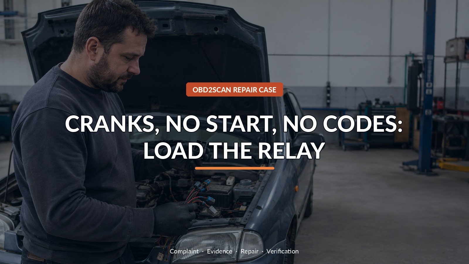
Cranks, No Start, No Codes: Load The Relay
A 2004 SEAT Arosa 1.4 TDI began by cutting out occasionally, then deteriorated into a complete crank-no-start. The starter turned the engine normally, but repeated cranking produced no DTC. Early signal captures made the camshaft sensor look suspicious: its logic changed when the engine briefly ran, and one injector event seemed to disturb it. Replacing that sensor would have been understandable—and wrong. The cam signal was being starved along with several other circuits.
This is the kind of problem where a circuit tester is useful only after the shared feed is identified. A device such as the MRCARTOOL B550 can help check accessible power, ground, polarity and voltage drop on a known low-voltage branch. B550 can help a trained user check identified 9–30 V power, ground, polarity and voltage drop on accessible circuits; it cannot safely feed unknown ECU or injector circuits, capture several fast signals at once, or prove relay contact quality without a representative load.
The decisive move was to zoom out from one odd waveform and follow the power diagram. The cam sensor, engine controller and injector-related circuits all depended on the engine control relay. Injector current then supplied the load that exposed resistance hidden inside that relay.
Quick answer: The Arosa’s cam signal was a victim. Injector load pulled a shared relay feed as low as 4.3 V; replacing the damaged engine-control relay restored voltage and starting.
In this guide
- A clean code memory did not make this a fuel-only no-start
- Start with cause and effect during cranking
- The cam signal was a victim, not yet a culprit
- Follow the diagram to the shared supply
- Use injector demand as the load test
- Open the relay only after the voltage path points there
- Fit the relay and repeat the same cranking capture
- Keep this result specific to this Arosa
A clean code memory did not make this a fuel-only no-start
No-code diesel no-starts often prompt immediate questions about rail pressure, immobilizer authorization and engine speed. Those were legitimate branches, but the capture already contained a more unusual relationship: sensor behavior changed in step with injector demand. Rather than treating the lack of codes as proof the ECU saw nothing wrong, the technician recorded crank and cam position plus injector activity together. A module with an unstable supply may not remain awake or coherent long enough to store the code a fault chart expects.
Start with cause and effect during cranking
During cranking, a very narrow drop appeared in the cam signal as an injector was driven. When the engine happened to start, the cam signal’s bias changed from 5 V to 0 V and became logically correct. That could still fit a failing cam sensor, but it did not explain why injector load seemed involved. A signal can be malformed because the sensor is defective, because its ground moves, or because its supply collapses. Checking all three is more informative than judging the signal wire alone.
The cam signal was a victim, not yet a culprit
The diagram showed that the cam sensor received battery voltage from the engine control relay. That feed was shared with other sensors and actuators and ultimately supported injector operation. This changed the case from “test one cam sensor” to “test one supply feeding several dependent circuits.” A shared-feed map is especially valuable on an old vehicle because corrosion, tired contacts and fractured solder can produce different symptoms depending on which component draws current at that moment.
Follow the diagram to the shared supply
With the engine briefly idling and beginning to stumble, the supply voltage dropped in direct response to injector current. One event pulled it to about 4.3 V while the circuit still tried to deliver roughly 11 A. Other injector events produced healthier current yet still knocked the feed down from battery voltage. That is a real loaded failure. An ohmmeter applied with the circuit asleep might have reported continuity and missed the contact resistance that became destructive only under demand.
| Evidence | Narrow conclusion |
|---|---|
| Cam signal disturbed during injector activity | Sensor may be a victim of another circuit |
| Several consumers share the relay feed | One upstream resistance can create many symptoms |
| Supply falls as injector current rises | Fault appears under load, not merely in continuity |
| New relay restores full voltage and shorter cranking | Repair corrects both cause and symptom |
Use injector demand as the load test
The relay was now the next physical checkpoint, not because this model has a magic relay rule, but because every affected consumer met at its output. Inspection found solder-joint fatigue, poor contacts and evidence of arcing on the circuit board. The extra resistance acted like an unwanted voltage divider: voltage was spent inside the relay instead of reaching the sensors, ECU and injector system. That explained both the deteriorating no-start and the apparently unrelated cam-signal disturbance.
Open the relay only after the voltage path points there
The correct repair was a replacement engine control relay, followed by inspection of its socket and terminals. A loose or heat-damaged terminal can ruin a new relay, so the housing should not be assumed healthy merely because the old relay contains visible damage. The circuit must also be returned to its original protection; bypassing a control relay or feeding an ECU branch directly can remove safeguards and create a much more expensive failure.
Fit the relay and repeat the same cranking capture
After the replacement, the shared supply held full battery voltage, cranking duration shortened and running stabilized. The cam-sensor dropout seen earlier no longer appeared because the sensor now had enough voltage while the injector circuit consumed current. That before-and-after relationship is stronger than “the engine started once.” It shows the new relay corrected the electrical condition that had caused the symptom.
Keep this result specific to this Arosa
Another Arosa that cranks but will not start may still have a genuine cam sensor, immobilizer, fuel-pressure or mechanical problem. This case supports a broader habit, not a shortcut to one part: when one actuator’s current changes another sensor’s signal, identify what they share. Test voltage while the circuit works hardest, then inspect the junction the diagram identifies. Do not rely on a clean DTC list or an unloaded continuity beep to declare a supply healthy.
The Arosa did not need a collection of sensors. It needed one tired electrical junction to be judged under the conditions that made it fail. Stop repeated cranking if the starter, cables or battery begin to overheat. For anyone handing a similar no-start to a shop, mention whether it evolved from intermittent cut-outs and whether the engine ever fires briefly. Those details help the technician capture the transition and verify the repaired supply instead of starting after the evidence has disappeared.








Comments 0
Questions, fixes, and real-world diagnostic notes from readers.
Be the first to share a diagnostic result or ask a follow-up question.