
How to Choose and Use AUTOOL AST Brake Bleeder Adapters

The AUTOOL 17-Piece Brake Fluid Changer Adapter Set solves a narrower problem than the parent machine: it must be the right part, fitted to the right interface and verified before normal work resumes. The useful question is not “does it look close?” but “do model, dimensions, connector, position and service purpose all agree?” Use the checks below to build a repeatable selection and fitting record without assuming that similar-looking parts are interchangeable.
Quick answer: Compare the adapter number, diameter, height, tabs or threads and connector with the vehicle reservoir before adding pressure. Select an adapter that locks squarely and compresses its seal evenly without cross-threading or rocking. Protect paint from brake fluid, start with the bleeder depressurized, attach the adapter by hand, connect the hose with its valve closed, then introduce only the pressure specified by the vehicle and bleeder instructions. Inspect for seepage before opening a wheel circuit. Stop immediately for fluid at the cap, a lifting adapter, a damaged reservoir neck, a hose that will not latch or a pressure loss that cannot be explained.
In this guide
What the AST brake bleeder adapters includes—and what it does not prove
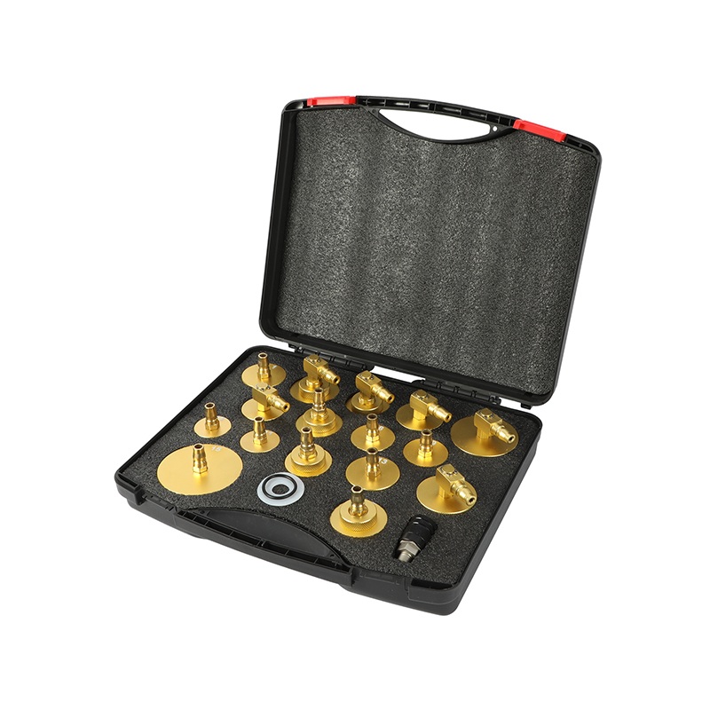
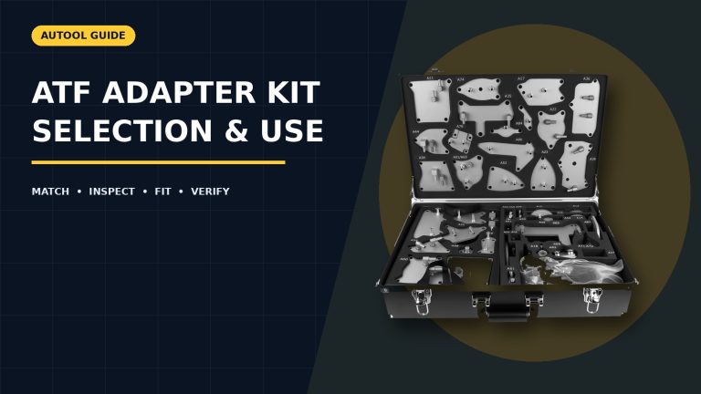
For this product, confirm the following items before fitting: 17 numbered reservoir adapters; quick connector; seals; storage case; compatible AST bleeder hose.
- The current page describes 17 reservoir adapters plus a quick connector and storage case.
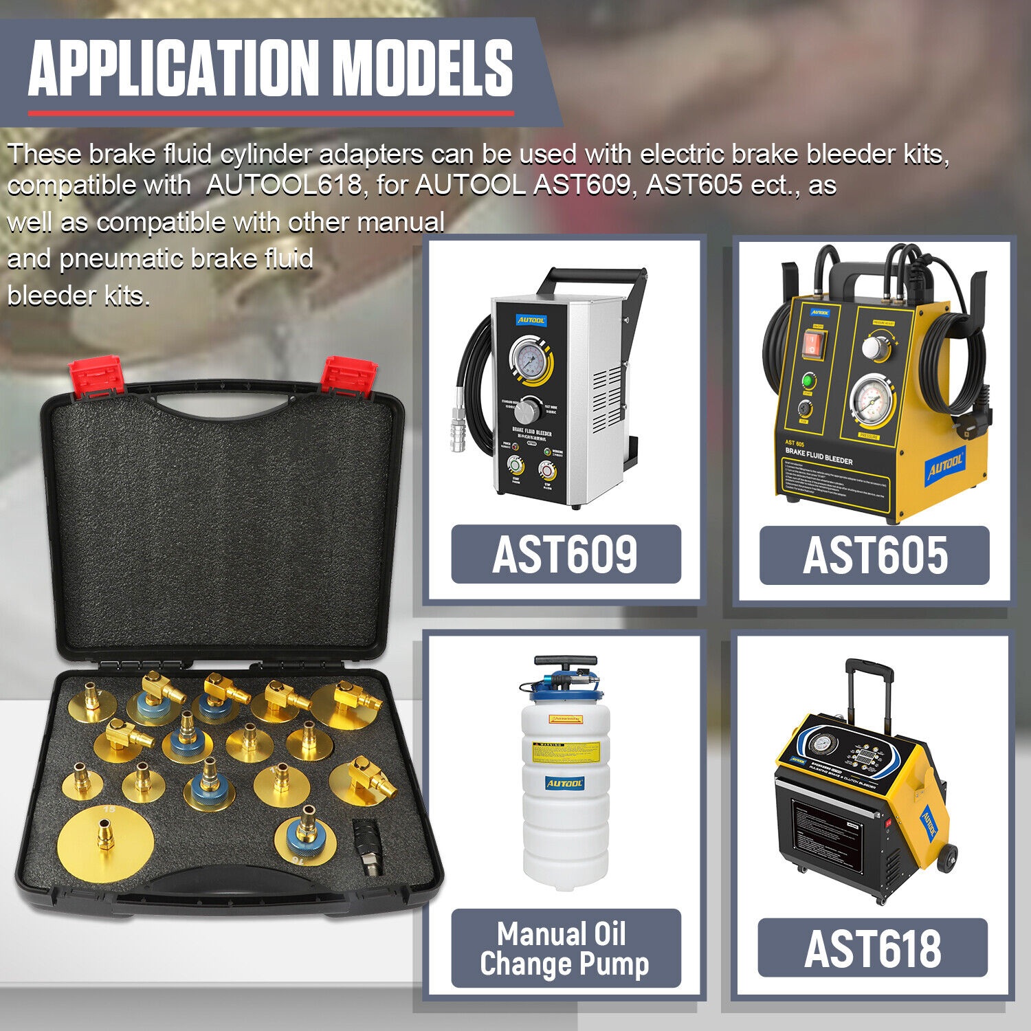
- It names AST612, AST609, AST605 and AST618 and also allows other manual or pneumatic bleeders only when connector and reservoir opening actually match.
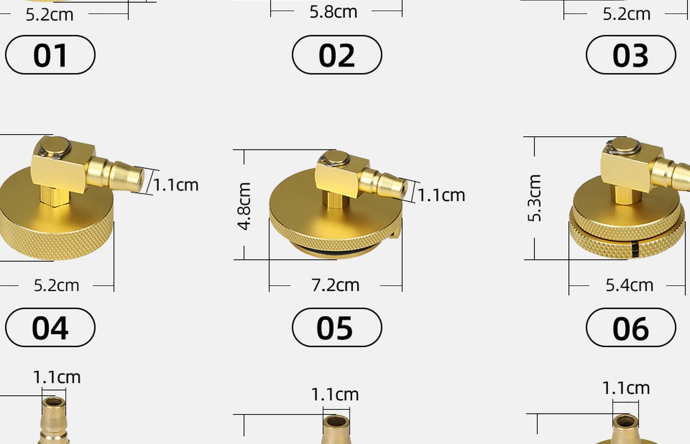
- The published size charts are selection aids; reservoir neck geometry, cap locking method, seal condition and quick-connector type still control the real fit.
Catalog names often group several selectable options on one page. Read the selected option, cart line and delivered label together. A family name establishes a product relationship, not universal compatibility. If one field is missing—model revision, dimensions, polarity, thread, capacity, position or connector—resolve it before altering the vehicle or equipment.
Build a match record before ordering or disassembly
Compare the adapter number, diameter, height, tabs or threads and connector with the vehicle reservoir before adding pressure. Select an adapter that locks squarely and compresses its seal evenly without cross-threading or rocking. Keep the exact machine instructions available; AUTOOL maintains its manual download center for current documents.
Save four photographs: the whole machine or vehicle location, the model/serial label, the installed part in its original orientation, and a close view of every identifier or connector. Record measured dimensions with units. This small evidence set prevents a common failure: selecting from a product thumbnail and discovering after disassembly that a connector, seal, position or revision differs.
Add a short acceptance line to the match record before ordering: what must be identical, what may legitimately differ, and which current manufacturer or supplier document confirms any revision change. For example, cosmetic color may change while a keyed connector and electrical rating must not; a service filter may carry a new supplier mark while its direction, medium and machine approval remain controlled. Writing that rule before the part arrives prevents confirmation bias during installation and gives a second technician something concrete to check.
Inspect the part and work area
The main avoidable consequence is brake-fluid spills, reservoir damage, air entry or an incomplete brake bleed. Open the package on a clean bench. Check for shipping damage, corrosion, bent pins, cut insulation, cracked plastic or glass, flattened seals, damaged threads and missing hardware as applicable. Compare the new and installed parts side by side without removing protective caps until needed. Do not grind, stretch, splice or shim a nearly matching part to make it fit.
Prepare containment and personal protection for the actual system. Brake fluid, coolant, transmission fluid, test fluid, refrigerant equipment, batteries, wheels and mains-powered chargers each demand different controls. The parent machine and vehicle procedure controls pressure, voltage, fluid, lifting, fasteners and calibration; an accessory listing cannot replace those instructions.
Step-by-step matching, fitting and verification workflow
1. Confirm authority, model and job scope
Confirm that the vehicle or equipment is authorized for service. Write down the exact model, serial or VIN-linked component identity and the reason for the work. Define whether the goal is selection, external accessory fitting, consumable replacement, internal repair or post-repair verification. If the job crosses into energized, pressurized, refrigerant, fuel, brake, lifting or internal electronic work, use the required competent person and facility.
2. Freeze the current configuration
Before disconnecting anything, photograph cable routing, hose direction, adapter position, seal orientation, fastener order and display state. Label identical connectors. Record any fault code or repeatable symptom under safe conditions. A configuration record is more useful than memory when a replacement option contains several similar pieces.
3. Compare the old part, listing and replacement
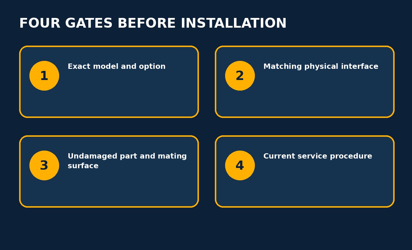
Compare every available identifier and physical datum. Check mating shape, keying, thread or clamp range, overall length, sealing diameter, pin count, polarity, voltage/current rating, flow direction and model-position designation as applicable. Require agreement on function and interface, not only color or enclosure shape. Resolve any conflict with the supplier or current service documentation.
4. Make the system safe
Return the parent equipment to its normal stopped state. Release pressure, cool components, contain fluid, support the vehicle, disconnect the approved power source or apply qualified electrical isolation as the applicable instructions require. Verify the safe state rather than assuming a switch or app command removed every energy source.
5. Inspect and prepare mating surfaces
Clean the interface without pushing contamination into an open system. Inspect threads, sealing lands, electrical terminals, mounting inserts, glass supports, hose ends and retaining features. Replace a damaged companion surface instead of asking the new part to compensate for it. Use only a lubricant or seal treatment approved for the exact fluid, material and system.
6. Fit by hand before applying force
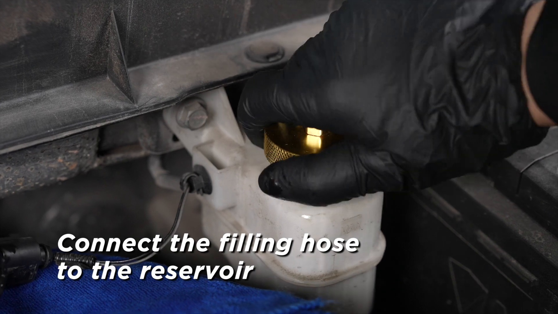
Protect paint from brake fluid, start with the bleeder depressurized, attach the adapter by hand, connect the hose with its valve closed, then introduce only the pressure specified by the vehicle and bleeder instructions. Inspect for seepage before opening a wheel circuit.
A correctly selected part should reach its intended seat predictably. Threads should start by hand; keyed connectors should align before being pushed; seals should remain centered; clamps should sit square; and clips or collars should lock without a pry tool. If force is needed to make geometry agree, stop and revisit selection or orientation.
7. Support hoses, cables and service loads
Route flexible connections with enough slack for the normal movement but away from heat, sharp edges and rotating parts. Do not let a hose or cable hang from a small adapter or connector. Apply operating pressure, current, flow or mechanical load gradually while observing the interface. The accessory must remain stable when an adjacent hose or cable is gently repositioned.
8. Perform the exact parent-machine procedure
Use the current vehicle and parent-machine instructions for settings, sequence, service fluid, pressure, electrical test, tightening values and calibration. Do not import a setting from a different model. Record the actual configuration used so the result can be repeated during the next service check.
9. Stop at the first abnormal sign
Stop immediately for fluid at the cap, a lifting adapter, a damaged reservoir neck, a hose that will not latch or a pressure loss that cannot be explained. Also stop for unexpected heat, odor, noise, pressure loss, unstable readings, arcing, fluid leakage or a connection that changes behavior when touched. Correct the cause before continuing; repeated attempts can turn an identification error into damaged equipment.
10. Verify before full operation
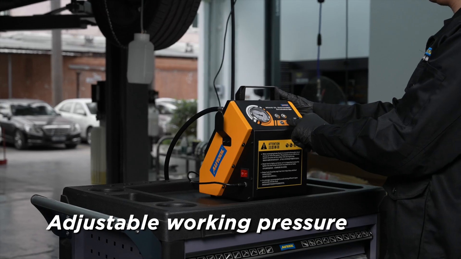
Begin with the lowest-risk functional check available: an open-air camera image, a static seal check, a de-energized fit inspection, a low-pressure leak check, stable diagnostic-interface power or a hand-tight fastener review as applicable. Then perform the exact machine’s self-check, calibration or controlled operating test. A part that merely powers up has not necessarily passed flow, insulation, seal, measurement or load verification.
11. Reinspect after the first cycle
Stop the equipment and inspect the interface again after the first controlled cycle. Look for witness marks, looseness, seepage, movement, cable heating, seal extrusion or changed readings. Recheck fluid level, case inventory and protective covers. Where the service procedure requires a second torque, calibration, electrical safety test or leak test, complete it with the specified instrument.
12. Label, clean and store
Record the installed part, date, machine/vehicle identity, symptom, corrective action and verification result. Clean reusable adapters with compatible materials, dry passages, protect connectors and return each piece to its indexed case position. Quarantine a damaged or uncertain part so it cannot be selected during the next job.
Troubleshooting
| Symptom | Check first | Next action |
|---|---|---|
| Part looks correct but will not seat | Exact option, orientation, keying, thread/diameter and obstruction | Remove without force and repeat the match record |
| Connection leaks or moves | Seal condition, mating surface, support and full engagement | Depressurize or de-energize; correct the interface before retrying |
| Parent machine behaves differently | Routing, polarity/flow, connectors, settings and original fault symptoms | Return to the before-service record and exact procedure |
| Replacement and old part labels differ | Revision supersession confirmed in current manufacturer information | Do not install until the difference is resolved |
| Result changes when hose/cable moves | Strain, intermittent conductor, loose connector or unstable adapter | Stop; repair support or replace the faulty connection |
| No safe verification method is available | Required test equipment and competent service level | Keep equipment out of service and escalate |
Final AST brake bleeder adapters checklist
- Exact model, revision and selected product option recorded
- Installed and replacement parts compared by identifiers and physical interface
- Mating surfaces, seals, threads, pins, cable or hose inspected
- Vehicle/equipment returned to the required safe state before fitting
- Part seated without improvised force, grinding, shimming or splicing
- Hoses and cables supported away from heat, motion and sharp edges
- Parent-machine procedure—not a neighboring model—supplied settings and sequence
- Controlled leak, power, function, calibration or mechanical check completed
- No heat, odor, leak, movement, unstable reading or damaged companion part remains
- Work record and photographs saved; removed or uncertain parts quarantined
A support part earns confidence through traceable matching and a controlled result, not through appearance. When the model, interface, condition and exact procedure all agree, the AST brake bleeder adapters can return the parent system to useful service without importing avoidable uncertainty into the next diagnosis or repair. Before the next service, another technician should be able to identify the installed option, find the applicable instructions and understand the last verification result without reconstructing the job from memory.


Comments 0
Questions, fixes, and real-world diagnostic notes from readers.
Be the first to share a diagnostic result or ask a follow-up question.