
How to Use the MRCARTOOL V309 GDI Fuel Injector Cleaner and Tester

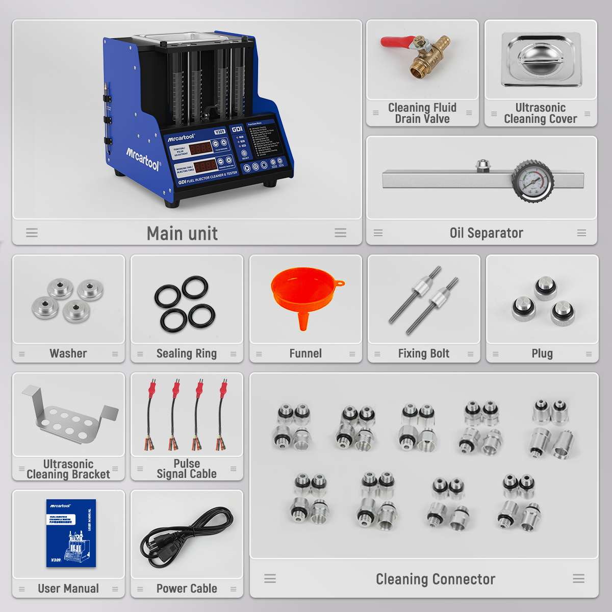
The MRCARTOOL V309 GDI fuel injector cleaner and tester adds selectable 12 V, 70 V and 120 V injector drive to a four-cylinder ultrasonic cleaning and test bench. That extra electrical range makes identification more important, not less: verify the exact injector, connector, adapter, drive voltage and test pressure before power. Clean in the separate ultrasonic tank, build a square sealed rail, prove leakage control and compare spray or collected volume only under identical settings.
Quick answer: Use the delivered nameplate and physical machine as the primary reference. Fill by the actual level window and cylinder graduations—not by conflicting online capacity claims. Never run the ultrasonic tank dry or immerse a pulse connector. Select 12 V, 70 V or 120 V only from verified injector data. Keep cleaning agent and test agent separate, clamp all four channels squarely, set injector-specific pressure, prove external sealing first, then compare leakage, pattern and volume.
In this guide
Identify your V309 configuration before filling it
The retained V309 manual lists AC 110/220 V ±10%, 50/60 Hz supply variants, a 40 kHz/70 W ultrasonic system, four 110 ml cylinders and 0–0.6 MPa system pressure. However, current official materials disagree on nominal tank and cylinder capacity: the manual says 2,000 ml cleaning-tank capacity, the current parameter graphic says 1,600 ml, and the product-page copy says 1,300 ml with 140 ml cylinders. None of those numbers should be used as a blind fill target.
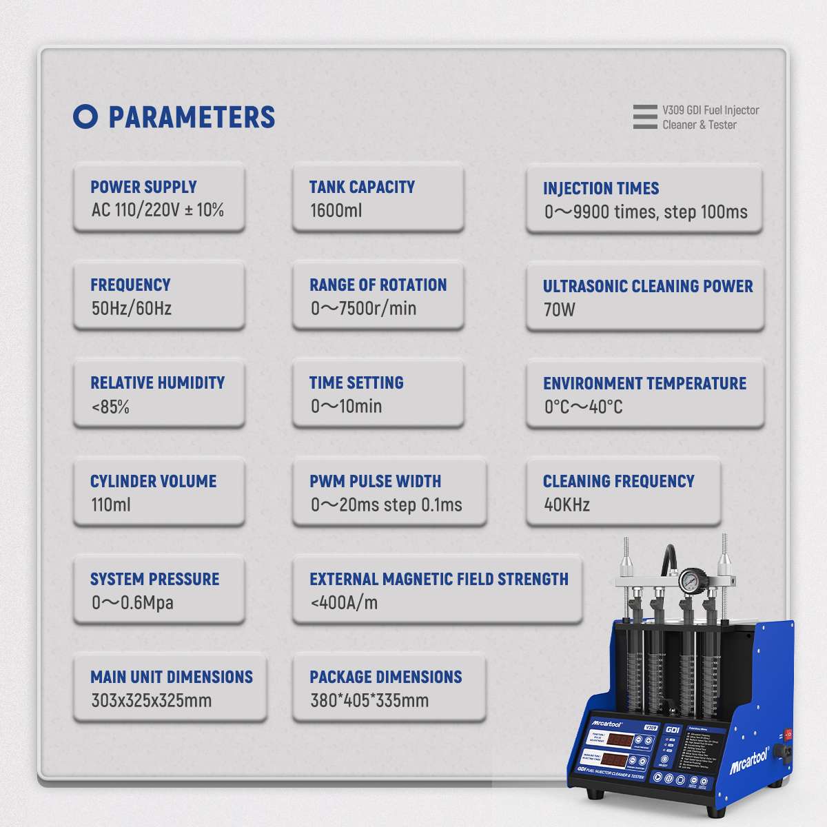
Configuration rule: Read the nameplate, reservoir window, cylinder graduations, valve labels and panel on the machine in front of you. If they disagree with the downloaded PDF or product page, stop and obtain serial/batch-specific instructions. Never add fluid merely to reach a web-listed capacity.
The V309 is Class I equipment and needs an uninterrupted protective ground. Match the outlet and fuse to the delivered nameplate. Do not use a damaged cord, wet extension connection or an adapter that defeats grounding.
- Work in a dry, bright, well-ventilated and ignition-free area. Keep cigarettes, sparks, flames and hot ignition sources away.
- Wear splash-rated eye protection and fluid-resistant gloves; keep other people and animals outside the immediate work zone.
- Inspect the power cord, hoses, pressure gauge, glass cylinders, rail, valves, leads, adapters and injector seals. Stop for cracks, damaged insulation or leakage.
- Identify every injector by part number and cylinder; obtain verified drive voltage, connector, pressure range and service tolerance.
- Use dedicated ultrasonic injector cleaning agent and separate injector test agent. Never substitute gasoline, kerosene or an unidentified solvent.
Step 1: Match the injector and voltage family
The V309 panel provides 12 V, 70 V and 120 V selections. These are different injector-drive outputs, not low/medium/high cleaning levels. A standard electromagnetic port injector may use the 12 V path, while supported high-pressure injector types may require a higher-voltage drive, but the label GDI alone does not select 70 V or 120 V for you. Use exact injector data and the matching delivered cable.
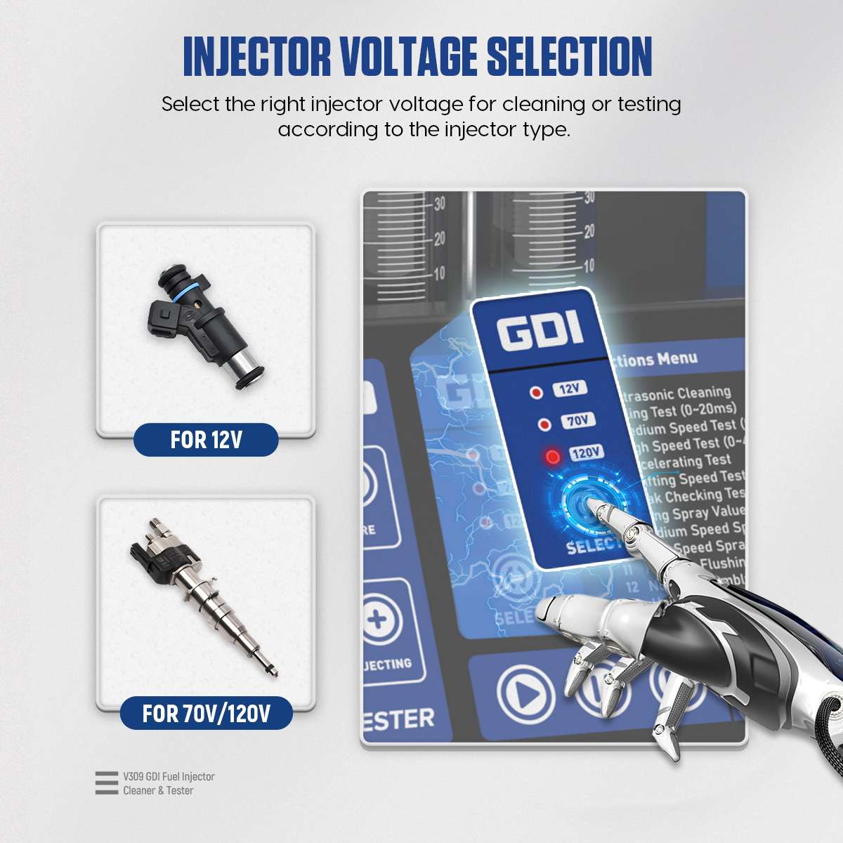
Stop: If drive voltage is unknown, do not energize the injector. The wrong selection can damage the injector or tester and can make every later spray or flow observation meaningless.
Step 2: Remove, inspect and pre-clean
Release vehicle fuel pressure and remove the injectors by the vehicle procedure. Keep their cylinder identity. Inspect inlet, nozzle, body, connector and every O-ring. Replace a cut, hard, flattened or swollen seal before any pressure test. Remove loose exterior contamination with approved cleaner and a soft cloth without pushing debris into an opening.
Step 3: Load and run the ultrasonic tank
Place the cleaning bracket in the ultrasonic tank and support up to four compatible injectors in its holes. Add only dedicated injector ultrasonic cleaning agent to the level specified by the physical tank and delivered instructions. The product page says the liquid should cover the injector needle area while the manual says it should cover the bracket bottom; in every case, keep pulse connectors and cable plugs above the liquid.
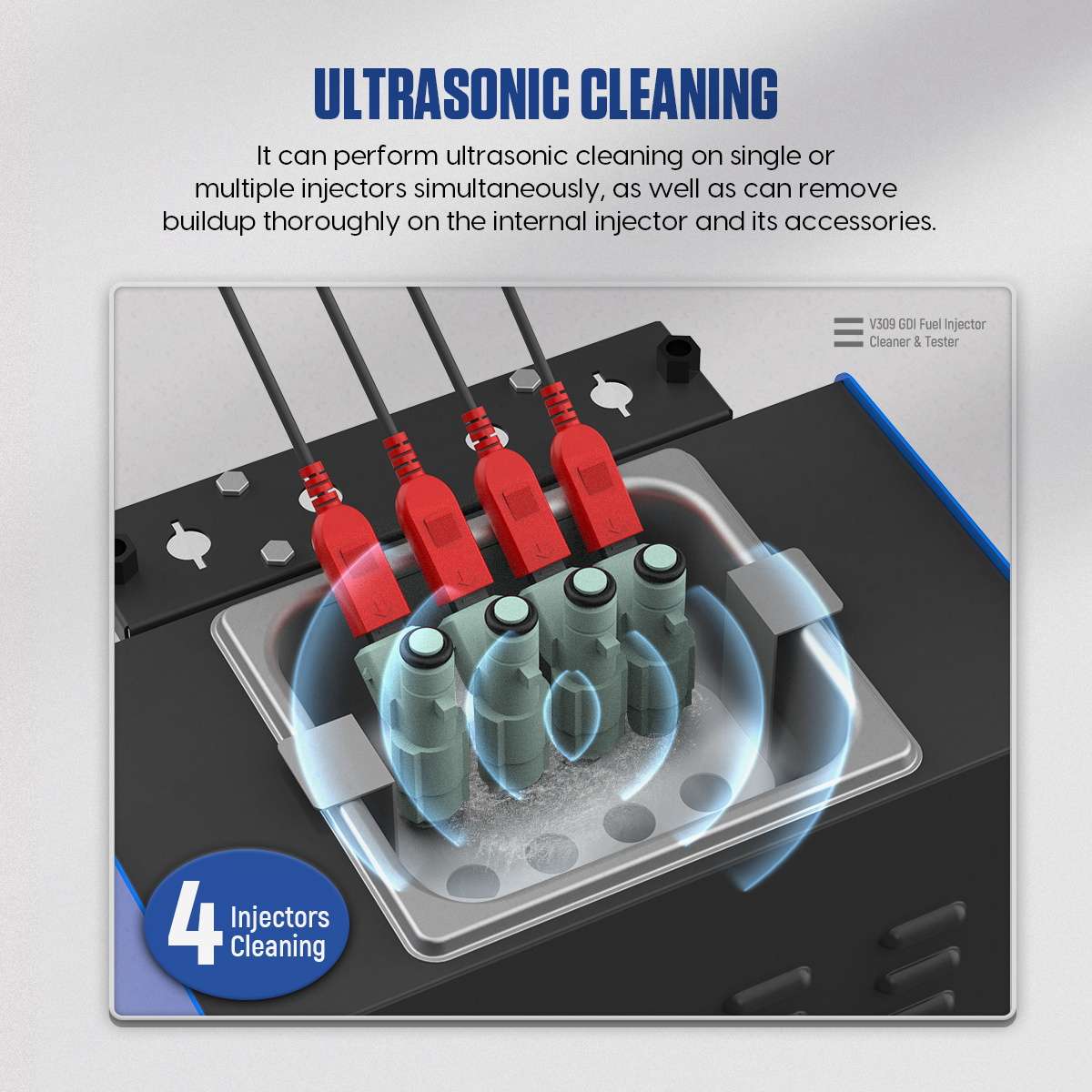
Select 01 Ultrasonic Cleaning, set the working time and connect only the required pulse leads while output is stopped. The manual gives 10 minutes as the default; the current product page warns against continuous ultrasonic operation beyond 30 minutes. Start the control program, enable the separate ultrasonic switch and observe the process. Use the heater only when the approved fluid and delivered instructions permit it.
At the end, switch off ultrasound and heat, remove the injectors carefully, let excess cleaning agent return to the tank and wipe the exterior dry. Do not carry cleaning liquid onto the test rail or signal connectors.
Step 4: Fill the separate test circuit by level
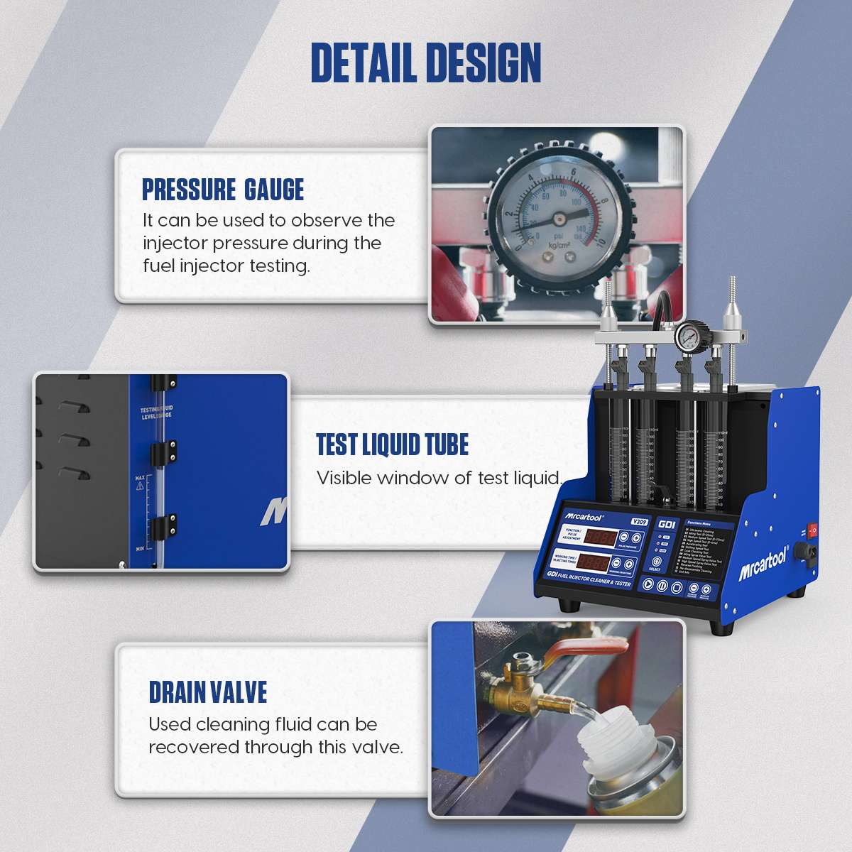
Confirm the test-agent drain valve and cylinder drain handle are in the preparation positions shown by the labels. Use the funnel to add approved test agent slowly through the level window. The manual mentions about 1,000 ml, but the conflicting reservoir-capacity claims make the physical MIN/MAX window the safer control. Stop at the specified visible level and check the bench and cabinet for leakage.
Step 5: Build a square, sealed four-injector rail
Select adapters by exact injector inlet and test direction. Install the top-feed connectors in the oil rail, apply only a light film of compatible lubricant to sound O-rings and insert the injectors straight. Plug or cap every unused flow path supplied for the configuration. Place the rail horizontally on the supports and tighten both locking rods evenly so each nozzle remains centered over its cylinder.
Connect the oil-supply hose only after the rail is mechanically secure. Connect each signal lead to its mapped injector with the machine stopped, and keep every electrical joint dry. The assembly must stand without a person holding it. Stop if a rail rocks, an O-ring is visible, a hose enters crooked, a nozzle points outside a cylinder or a connector is wet.
Step 6: Select voltage, function and parameters
Confirm the voltage indicator first, then use the function/pulse controls to select the menu item and pulse width, the work/injection controls to set time or count, and the pressure controls to raise or lower system pressure. Use Start, Pause and Stop as labeled. Make every change while the setup remains observed.

| Menu | Purpose | Boundary |
|---|---|---|
| 01 Ultrasonic Cleaning | Clean supported injectors in the separate tank | Correct fluid, level, leads, voltage and time |
| 02–04 Idle / Medium / High | Observe pattern at fixed simulated conditions | Verified voltage, pressure, pulse width and time |
| 05 Acceleration | Automatic 750–7,500 rpm simulation | Secure setup and exact injector limits |
| 06 Variable Speed | Cycle 750, 4,500 and 7,500 rpm | Same injector set and controlled pressure |
| 07 Leakage | Observe nozzle closure and external sealing | Dry assembly, controlled pressure and time |
| 08–10 Spray Volume | Collect idle, medium and high-speed delivery | Same baseline, count, pressure and reading method |
| 11 Reverse Flushing | Flow approved cleaning/test agent through a supported injector in the reverse installation direction | Exact reverse adapters, injector approval and guarded collection required |
| 12 No-disassembly Cleaning | Operate only with the specified optional vehicle-cleaning accessories and vehicle procedure | Not a generic hose connection; do not improvise |
| 13 Unit Info | Display machine information | No injector test output intended |
The manual’s 0.25–0.30 MPa electronic-injection example and 0.3 MPa leakage example are not universal GDI settings. Use the exact injector or service specification and stay within both that requirement and the machine’s 0.6 MPa limit. Higher electrical drive voltage does not imply a higher fluid-pressure setting.
Step 7: Prove sealing before observing spray
Start with the leakage function or the lowest-risk applicable test. Raise pressure gradually while watching the gauge, hose, rail, adapters, injector inlets and cylinders. Wetness at an adapter or rail is a setup fault; a droplet from a closed injector nozzle may indicate injector leakage. Stop and depressurize before deciding which one you are seeing.
After the external assembly stays dry, run the applicable fixed-speed program. Observe whether each injector opens, whether the pattern remains inside its cylinder and whether atomization is stable. Stop for movement, arcing, a hot connector, rapidly falling pressure, abnormal pump sound or fluid outside the cylinders.
Step 8: Compare collected volume
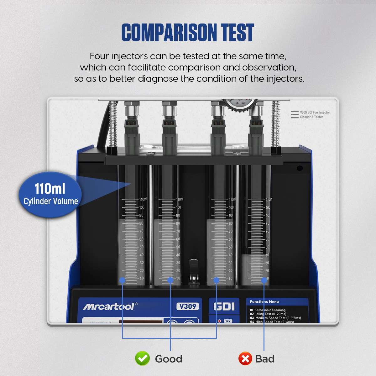
For Items 08–10, start with each physical cylinder at the same readable baseline, set the same injection count, collect all channels together and pause before any cylinder becomes too full. Let the liquid settle and read each meniscus at eye level. Record the actual graduated value; do not assume whether the cylinder is nominally 110 or 140 ml from web copy.
The manual mentions a 2 percent within-set deviation and then directs the operator to the injector technical manual. The controlled service tolerance remains the authority. A low result can follow an injector, signal lead, adapter restriction, trapped air, rail alignment or setup leak. Repeat with a documented, depressurized position/channel swap before condemning a part.
Step 9: Use reverse flush only with verified adapters
Item 11 reverses the injector installation direction so approved fluid can move against the normal flow path. Use it only when the injector construction, seal arrangement and supplied reverse adapters permit. Clamp the reversed injector as securely as a forward test, direct discharge into guarded collection and use the approved pressure. Never force a nozzle into a connector or reverse-flow an injector whose procedure prohibits it.
Item 12 is more restrictive. The manual describes no-disassembly cleaning through special optional parts connected for combustion-chamber or throttle cleaning. That is not permission to improvise a vehicle fuel connection. Use only the exact accessory kit and vehicle-specific isolation, supply and restoration procedure; otherwise leave Item 12 unused.
Step 10: Stop, depressurize and maintain
Press Stop, lower pressure and wait until the gauge and fluid behavior confirm no stored pressure. Switch off the ultrasonic/heater controls and main power, then unplug the machine before loosening a rail, hose, injector or adapter. Remove signal leads by their connector bodies and keep wet parts away from electrical sockets.
- Return reusable test agent only when it remains serviceable and uncontaminated; never mix it with ultrasonic cleaning agent.
- Drain separate fluids into compatible labeled containers and dispose of contaminated material as hazardous waste under local rules.
- For long storage, drain the test tank. The manual calls for a small clean-fluid rinse, another drain and 1 L of fresh test agent at service time.
- Protect the quartz-glass cylinders from impact and store every voltage lead and adapter by identity.
- Record injector part number, voltage selection, adapters, pressure, pulse width, count, results and any setup swap used to verify a difference.
Use the current MRCARTOOL manual download page when the delivered nameplate, level window, cylinder markings, voltage panel, rail or accessory kit differs from this sequence.
Troubleshooting
| What you see | Check next |
|---|---|
| No display | Nameplate supply, protected ground, plug, main switch and fuse; do not open the cabinet. |
| Injector does not pulse | Verified 12/70/120 V selection, correct cable, dry connector, pulse width and controlled channel swap. |
| Pressure will not stabilize | Physical fluid level, valve position, supply hose, rail seals, unused ports and external leakage. |
| One cylinder reads low | Equal baseline, adapter restriction, trapped air, rail alignment, signal channel and identical parameters. |
| Reverse flush leaks | Stop and depressurize; verify injector approval, reverse adapter, O-ring direction and clamping. |
| Fluid becomes dirty | Drain and replace it before contamination reaches cleaned injectors or damages the pump circuit. |
Frequently asked questions
Does the V309 support every GDI injector?
No universal percentage proves exact compatibility. Confirm the connector, adapter, drive voltage, pressure range and procedure for the injector in front of you. The machine’s 12/70/120 V options and 0.6 MPa limit do not reproduce every direct-injection system.
Which V309 capacity is correct?
Official sources conflict, so do not use a nominal capacity as a fill instruction. Use the physical MIN/MAX window, cylinder graduations, nameplate and delivered serial/batch documentation.
Can the 70 V or 120 V selection be tried until the injector works?
No. Choose voltage from controlled injector data before connection. Trial-and-error voltage selection risks damage and invalidates the test.
Can cleaning agent be used as test agent?
No. Keep dedicated ultrasonic cleaning agent and injector test agent in their own circuits. The manual prohibits mixing them and prohibits gasoline, kerosene and unapproved substitutes.
Can Item 12 be connected directly to any running engine?
No. It requires the specified optional hardware and a vehicle-specific procedure for isolation, fluid supply, ventilation and restoration. Do not improvise that circuit.
Final V309 checklist
- Delivered nameplate, level window, cylinder graduations and protective ground confirmed
- Exact injector, adapter, connector, 12/70/120 V drive and pressure requirement verified
- Cleaning agent and test agent kept separate; no prohibited fluid used
- Pulse connectors kept above ultrasonic liquid and tank never run dry
- Rail, O-rings, injectors, hose and leads square, dry and independently secure
- External leak check passes before spray or volume collection
- All compared channels use the same voltage, pressure, pulse width and time/count
- Reverse flush or no-disassembly mode used only with verified hardware and procedure
- Pressure released and power isolated before disassembly
- Settings, physical graduations, results and verification swaps recorded
The V309’s wider injector-drive range is useful only when the setup is controlled. Identify the actual hardware, resolve capacity questions from physical markings, select voltage from injector data, keep fluids separate, prove sealing and compare all four channels under the same conditions. That workflow makes the result traceable and keeps a configuration mismatch from looking like an injector fault.


Comments 0
Questions, fixes, and real-world diagnostic notes from readers.
Be the first to share a diagnostic result or ask a follow-up question.