
How to Use the FXTUL UNT50 Ultrasonic Fuel Injector Cleaner

The FXTUL UNT50 cleans removed fuel injectors in an ultrasonic bath while its pulse signal lead actuates the injector. The controlled order is to identify the correct machine and injector, complete the bracket, lead and liquid setup with the power switch off, fill the bath before energizing it, run one monitored timed cycle, then switch off, unplug, drain and inspect the injector before it returns to the vehicle.
UNT50 is a cleaner, not a measuring bench. It does not show comparative flow, spray pattern, leakage or test pressure. A clean injector can still have an electrical, sealing or mechanical fault, so cleaning must not replace the vehicle’s diagnostic and service procedures.
Updated August 28, 2026.
In this guide
Decide whether the UNT50 fits the job
| Situation | Decision | Why |
|---|---|---|
| A removed motorcycle fuel injector fits the supplied bracket and pulse connection, and its materials are compatible with the chosen ultrasonic fluid | Continue with this guide | This is the exact task supported by the UNT50 setup |
| Fuel pressure has not been relieved or the injector is still installed | Stop and use the vehicle service procedure first | UNT50 is an off-vehicle bath; it is not an on-car flushing tool |
| You need to compare flow, inspect spray pattern under controlled pressure or check static leakage | Use an appropriate injector test bench or qualified service | UNT50 has no measuring cylinders or pressurized test circuit |
| The unit’s marked input voltage does not match the available grounded supply | Do not connect it | A 110 V or 220 V marking is a delivered-unit requirement, not an automatic dual-voltage setting |
| The cord, plug, pulse lead, case, bath, drain or injector connection is damaged | Do not operate it | Liquid, mains power and a damaged connection are an unsafe combination |
| The liquid is gasoline, an unidentified solvent or is not approved for ultrasonic cleaning and the injector’s materials | Do not put it in the bath | The visual appearance of a liquid does not prove chemical compatibility |
Prepare the work area, injector and supplies
Have the exact vehicle service information, the removed injector, the UNT50 cleaning bracket and pulse signal lead, injector-safe ultrasonic cleaning fluid, eye protection, chemical-resistant gloves, absorbent material and a labeled container for drained liquid. Use the fluid maker’s directions for concentration, temperature, contact time, filtration, reuse and disposal.
Place the machine upright on a stable, level, dry surface in a ventilated area. Keep at least 200 mm of clearance from walls or other objects. Do not smoke, and keep open flame at least 2 m away. Do not work in rain, on a wet floor or beside an open container of gasoline or another combustible liquid.
The manual lists an ambient operating range of -10°C to +40°C and relative humidity below 85%. More importantly, the operator must be able to keep the machine exterior, plug, outlet and pulse connection dry while controlling the liquid path from filling through final draining.
FXTUL UNT50 step-by-step procedure
Step 1: Confirm the model and electrical rating
Read the label on the machine and confirm UNT50. Check the marked input voltage against the local grounded AC supply. The product is supplied in 110 V and 220 V versions; never infer that one unit accepts both voltages unless its own rating label expressly says so.
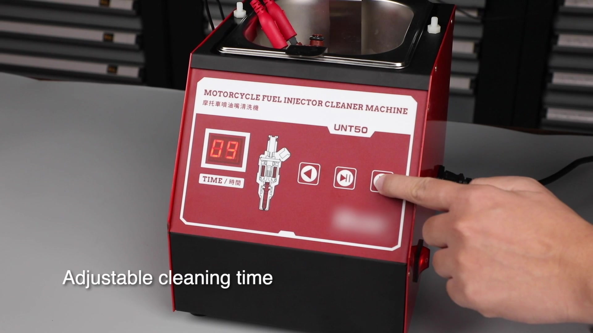
Identify the ultrasonic bath, display, left and right time buttons, start/pause button, power switch, power inlet, pulse-lead socket, bracket locating nuts and side drain port before adding liquid.
Completion check: You can name every control you will touch, and the machine’s voltage matches the grounded outlet.
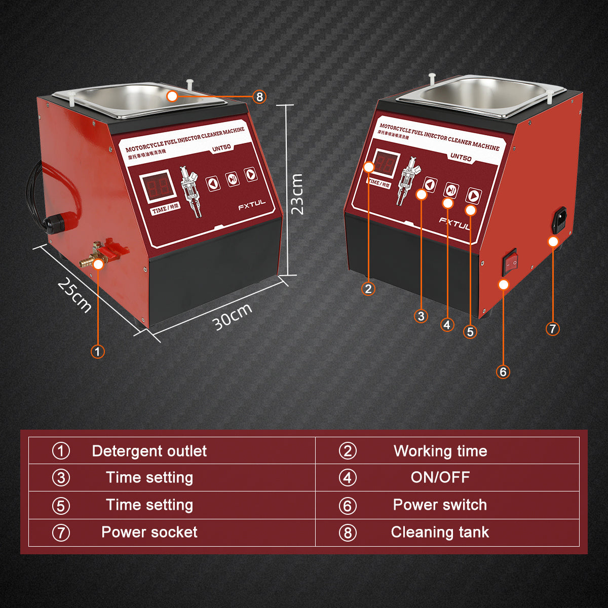
Step 2: Complete the vehicle-side removal procedure
Use the vehicle manufacturer’s procedure to relieve fuel pressure, isolate electrical power where required, disconnect the injector and remove it. Keep fuel away from the UNT50 work area. Cap or protect open vehicle fuel-system connections as the service procedure directs.
Do not use this article to guess a fuel-pressure relief point, connector latch, rail-removal order or fastener torque. Those details change by vehicle and engine.
Stop: If fuel continues to escape, the injector cannot be removed without force or the service information is unavailable, do not move the part to the cleaning bench.
Step 3: Identify the injector and its cleaning boundary
Confirm that the injector body sits securely in the supplied bracket and that the pulse lead fits without bending pins, spreading terminals or loading the plastic connector. Check the injector body, inlet, outlet, connector and visible filter area for cracks, corrosion or impact damage.
Follow the vehicle or injector procedure for O-rings, seals, caps and filter components. Do not immerse an electrical connector or a material that the fluid maker excludes. Keep removed seals identified so the correct approved replacements return to the correct injector.
Common mistake: Treating physical bracket fit as proof of electrical and chemical compatibility. All three conditions must be correct.
Step 4: Verify the cleaning fluid and drained-liquid route
Read the cleaning-fluid label. It must be suitable for ultrasonic use and compatible with the injector body, internal components and any item that will contact the bath. Confirm its ventilation, PPE, temperature, time and disposal requirements.
Prepare a stable, labeled receiving container at the drain side of the machine. The container must hold the planned drain volume without being moved while full. Close and secure the drain before filling the bath.
Stop: Do not use gasoline, an unidentified workshop liquid or a chemical merely because its color resembles the liquid shown in a product image.
Step 5: Inspect the UNT50 before every cycle
With the machine unplugged and the power switch off, inspect the cord, plug, power inlet, case, bath, controls, pulse socket, signal lead, bracket, locating nuts and drain. The bath must be clean enough that old debris cannot be mistaken for contamination from the current injector.
Check that the machine stands without rocking and that the drain is closed without being overtightened. Wipe any moisture from the exterior and keep the cord away from the bath, hot parts, sharp edges and walkways.
Stop: A damaged cord, loose socket, cracked case, leaking drain, unstable bracket, damaged lead or previously dropped machine requires qualified inspection before use.
Step 6: Install and secure the cleaning bracket
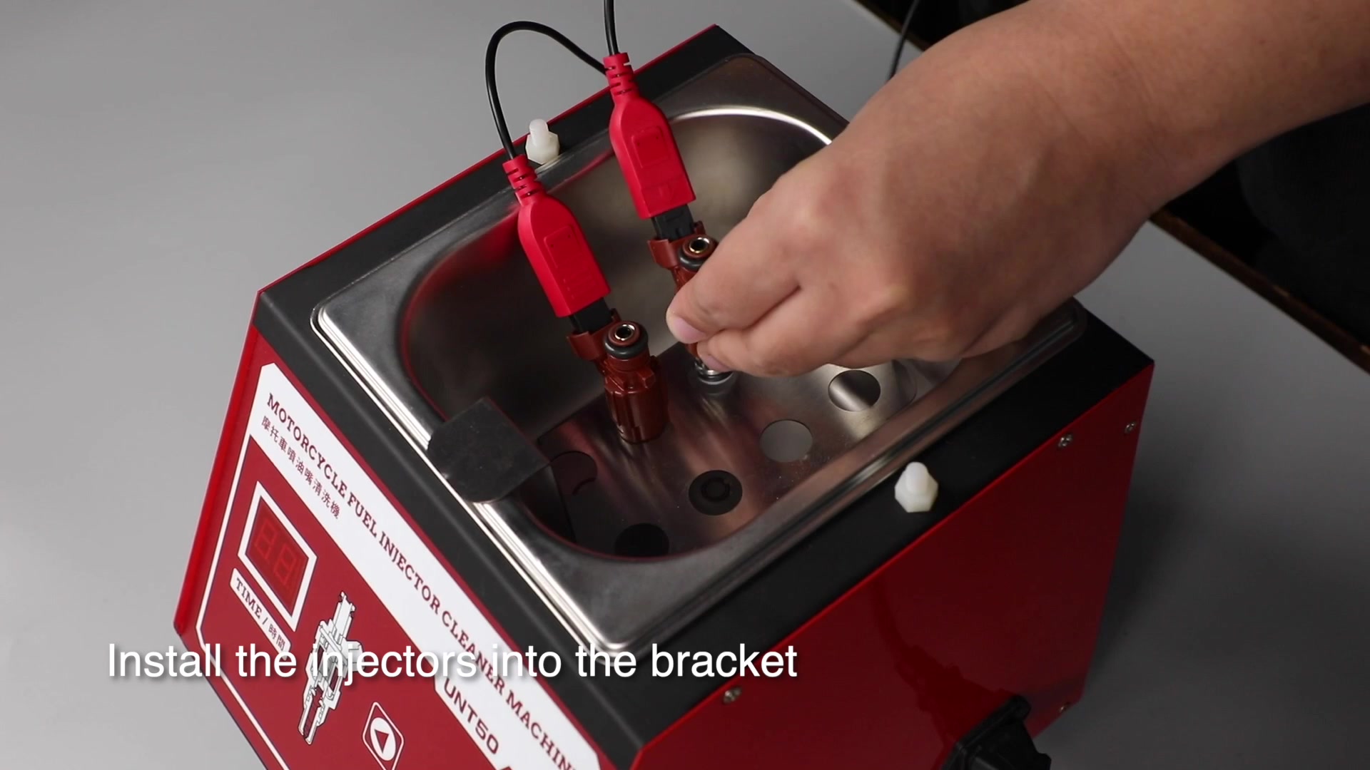
Place the cleaning bracket across the ultrasonic bath in the correct orientation and seat it on the locating points. Tighten the locating nuts only enough to prevent the bracket from shifting. Do not distort the bracket or use it as a handle for the machine.
Completion check: The bracket is level, cannot slide into the bath and leaves the injector’s electrical connection accessible above the planned liquid level.
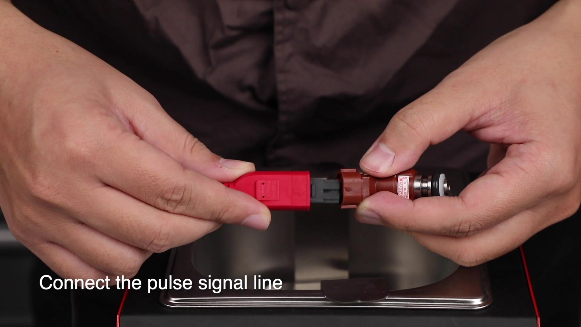
Step 7: Connect the pulse signal lead to the injector
Keep the power switch off. Join the appropriate pulse-lead connector to the injector without forcing it. Hold connector bodies rather than pulling on wires. Route the lead so it cannot fall into the bath or lift the injector out of the bracket.
Seat the removed injector in the bracket opening with the cleaning end directed into the bath. If more than one injector is being cleaned, each one must be independently supported and connected without crowding or contact that could damage a body or lead.
Completion check: The injector cannot tip, the lead has slack, and no electrical connector is in the planned wet zone.
Step 8: Fill to the specified needle-valve depth
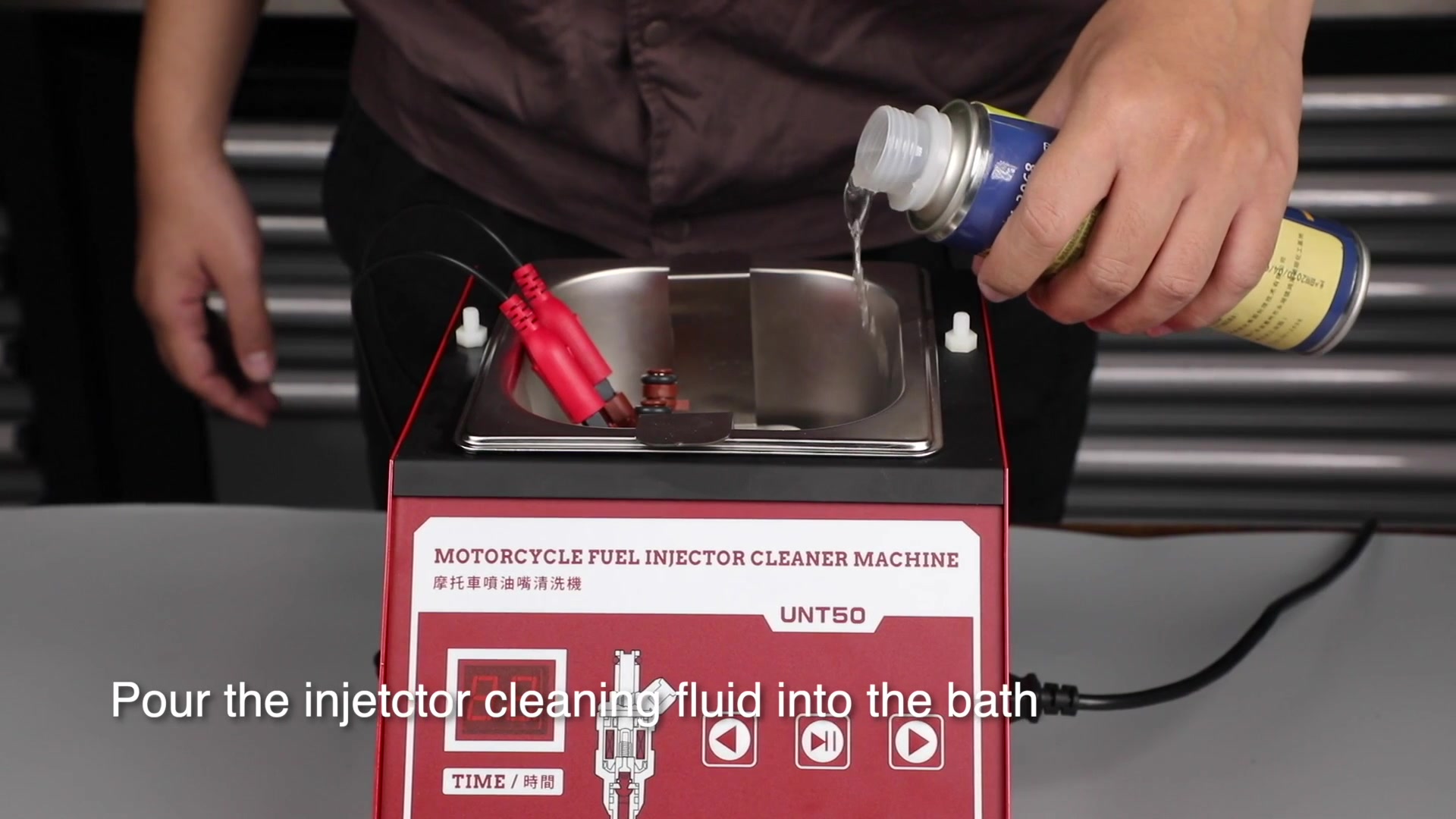
Pour the prepared ultrasonic cleaning fluid slowly into the bath. The UNT50 instructions call for the fluid to cover approximately 20 mm above the injector’s needle-valve area. Use that task-specific depth instead of estimating from the bath’s outside size, and remain within any limit marked on the supplied bath.
Keep the injector electrical connector, pulse connection, machine controls, power inlet and exterior dry. Stop pouring if the bracket moves, the receiving drain leaks or the liquid approaches an electrical connection.
Critical check: The ultrasonic bath must contain the required liquid before the ultrasonic function starts. Never run the bath dry.
Step 9: Make the final de-energized setup check
Verify that the drain is closed, the machine is stable, the bracket is locked, the injector is supported, the pulse connection is secure, the fluid depth is correct and every electrical surface is dry. Confirm that no open flame, smoking, fuel container or unrelated ignition source has entered the area.
Move the prepared drain container far enough away that it cannot be kicked or contaminated during the cleaning cycle, but keep it ready for shutdown.
Completion check: Nothing needs to be installed, tightened, repositioned or filled after power is connected.
Step 10: Connect grounded power and switch the unit on
With dry hands, connect the correct power cord to the machine and then to the matching-voltage grounded outlet. Keep the cord free of the bath and drain route. Turn on the main power switch.
Watch the display and listen for an abnormal electrical sound. Switching the unit on prepares the controls; do not confuse it with permission to run an empty or incorrectly filled bath.
Stop: If the display does not behave normally, a plug or cord becomes warm, a breaker trips, liquid is present on an electrical surface or there is a burning smell, switch off if safe, disconnect at the plug and remove the unit from service.
Step 11: Set a bounded cleaning time
Use the left or right arrow button to select the working time. UNT50 provides an adjustable 0–20 minute range, but 20 minutes is not a universal default. Choose a duration allowed by the cleaning-fluid instructions and appropriate for the injector and contamination condition.
If the injector or fluid supplier sets a shorter contact limit, that lower limit controls. Do not extend time to compensate for a damaged injector, incompatible fluid or absent ultrasonic action.
Common mistake: Starting at the maximum timer value without checking the fluid and injector requirements.
Step 12: Start the cleaning cycle
Press the start/pause button once. Confirm that the timer begins and that the injector remains seated in the bracket. The bath now runs for the selected time while the pulse lead actuates the injector.
Keep hands, tools and loose parts out of the bath during operation. Do not touch the liquid to decide whether the ultrasonic system is working.
Completion check: The timer is advancing, the setup remains stable and there is no liquid at the drain, case, power inlet or pulse connector.
Step 13: Monitor the complete cycle
Stay with the machine. Watch the bracket, leads, fluid level, bath, drain and display. A small change in the liquid’s appearance can occur as contamination is released, but it does not prove that an internal restriction or injector fault has been corrected.
Pause or stop the cycle if the injector moves, a lead loosens, liquid leaks, excessive heat develops, an unusual sound appears or the fluid maker’s condition limit is reached. Switch off and unplug before correcting a physical or wet connection.
Stop: Never continue by holding a loose injector or lead in place with your hand.
Step 14: Let the timer stop the cycle
At the end of the selected time, the UNT50 stops automatically. Confirm that the timer has ended and the ultrasonic action has stopped. Do not immediately reach into the bath or disconnect a wet part.
If you paused the machine early, record why. Do not automatically restart a new full cycle until the cause is understood and the fluid’s accumulated contact time remains acceptable.
Completion check: The cycle is stopped, the injector is still supported and no abnormal condition is present.
Step 15: Switch off and unplug before disassembly
Turn off the main power switch. Remove the plug by holding the plug body, not by pulling the cord. Keep the plug and cord end away from the bath and place them on a dry surface.
Allow the injector and liquid to settle or cool for the period required by the cleaning-fluid instructions. The power must remain disconnected while you remove the lead, bracket or injector.
Critical check: There is no power at the machine before a wet component is handled.
Step 16: Remove and inspect the injector
Lift the injector without dragging its connector or lead through the liquid. Support it over the bath until dripping has stopped, then disconnect the pulse lead by the connector body. Follow the cleaning-fluid maker’s instructions for rinsing, drying or residue removal; do not invent a rinse chemical.
Inspect the injector again for cracks, corrosion, damaged terminals and seal-land damage. Cleaning residue from the outside does not establish that the coil, valve, spray pattern or sealing surface works correctly.
Stop: A cracked body, loose terminal, damaged inlet, visible leak path or unresolved contamination requires further inspection, testing or replacement rather than vehicle installation.
Step 17: Drain and handle the used fluid
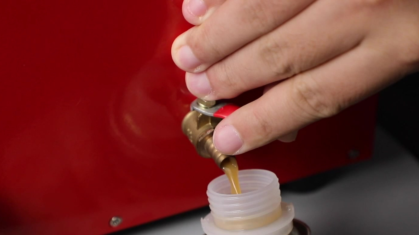
Place the labeled receiving container beneath the drain port. Open the drain under control and keep the outlet directed into the container until the bath is empty. Close the drain after flow has stopped and wipe the port without allowing liquid to reach the power inlet or switch.
Filter or reuse the liquid only when the fluid manufacturer expressly permits it and the contamination condition remains within its instructions. Otherwise, close and label the container and use the applicable local hazardous-fluid route. Never pour the liquid into a floor drain, sink, storm drain or an unverified supply container.
Common mistake: Assuming that “drainable” means “reusable.” The fluid instructions and contamination—not the machine—decide that.
Step 18: Clean, inspect and store the UNT50
With the unit unplugged and cooled, wipe the bath and exterior using methods compatible with the machine and cleaning fluid. Do not immerse the unit or direct water into the controls, pulse socket, power inlet or case. Leave the bath empty and dry for storage.
Inspect the cord, lead, bracket and drain for damage created during the job. Store the machine upright in a dry, ventilated location away from direct sunlight and rain. Empty the bath before transport, keep the original protective packaging where practical, do not invert the unit and do not exceed a 45° tilt during transport.
Completion check: The bath is empty, the machine is dry and unplugged, the cord and lead are protected, and no used liquid remains in an unlabeled container.
Verify the injector before it returns to the vehicle
Use the injector and vehicle service procedures to decide what inspection or bench testing is required. If the original complaint involved an imbalance, misfire, leakage, poor spray pattern or electrical fault, the correct next step may be resistance testing, a controlled flow/spray/leak test or qualified service. UNT50 alone cannot provide those measurements.
Install only serviceable injectors with the specified seals, lubricant, orientation and torque. Reconnect the fuel and electrical systems through the vehicle procedure, restore pressure under control and perform the prescribed leak check before starting or returning the vehicle to service.
Troubleshoot without bypassing a safety check
| Symptom | Safe check | Do not do |
|---|---|---|
| No display after switch-on | Switch off and unplug; verify the rating label, outlet, plug seating and visible cord condition | Do not open the case or bypass grounding |
| Injector does not appear to pulse | Switch off and unplug; inspect the exact injector-to-lead fit and lead condition | Do not force terminals or hold a loose connection by hand |
| No clear visible cleaning action | Confirm the bath contains fluid, the timer is running and the setup matches the exact machine instructions | Do not touch the bath, run it dry or extend time without a limit |
| Liquid leaks from the drain or case | Stop, switch off, unplug if safe and contain the liquid | Do not tighten a wet or energized fitting |
| Contamination remains after the cycle | Reassess fluid condition, injector compatibility and whether a further allowed cycle or a test bench is appropriate | Do not promise that repeated cleaning will repair a mechanical or electrical fault |
| Injector still causes a vehicle symptom | Continue diagnosis with vehicle-specific data and appropriate test equipment | Do not reinstall repeatedly or replace parts solely because the symptom persists |
What a complete UNT50 job looks like
A complete job starts with the exact UNT50 voltage and a compatible removed injector, completes bracket, lead and fluid setup while the switch is off, covers the needle-valve area by approximately 20 mm without wetting electrical connections, and runs only a bounded monitored cycle. It ends with power isolated, the bath drained, the machine dry and safely stored, the fluid correctly contained and the injector inspected or tested before vehicle reinstallation.
That separation matters: UNT50 completes an ultrasonic cleaning process. The injector and vehicle procedures decide whether the part is ready to return to service.


Comments 0
Questions, fixes, and real-world diagnostic notes from readers.
Be the first to share a diagnostic result or ask a follow-up question.