
How to Use the AUTOOL LM708 Refrigerant Recovery Machine

Use the AUTOOL LM708 by identifying the vehicle refrigerant before connection, selecting the matching R134a or HFO-1234yf circuit, verifying the correct oil requirement, and keeping that circuit traceable through recovery, repair, evacuation and measured charging. Connect with the engine and A/C off, recover first, confirm that pressure does not return, account for removed oil, repair and test the system, evacuate to the vehicle-specified acceptance gate, then charge the exact specified mass through the permitted port path. Use Automatic mode only after every input has been checked separately.
The LM708 automates refrigerant movement and records the result. It does not identify unknown refrigerant, decide whether a leak has been repaired, choose a compressor oil or replace the vehicle service procedure.
Updated August 27, 2026.
In this guide
What the current LM708 does
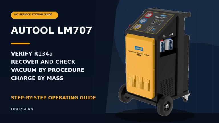
The current AUTOOL LM708 is a dual-system automotive A/C service station for R134a and HFO-1234yf. It has separate refrigerant tanks and quick connectors, a 7-inch touchscreen, PAG and POE new-oil bottles, a used-oil bottle, five weighing channels, vehicle-data lookup, service-record printing, manual functions and an automatic sequence.
Its principal jobs are refrigerant recovery and cleaning, evacuation, a pressure-decay check, controlled oil addition and measured refrigerant charging. It can use low-side, high-side or combined high-and-low-side charging when the exact vehicle procedure permits that path.
The two refrigerant systems are independent service paths; they are not permission to connect an unknown system and let the machine decide what it contains. Confirm refrigerant identity first and operate one selected circuit at a time.
Before you connect
Open the AUTOOL manual download center and obtain the LM708 manual that matches the rating plate, touchscreen and serial generation in front of you. Obtain the exact vehicle refrigerant label and current service information as well. Record the required refrigerant type and mass, compressor-oil chemistry and quantity rule, service-port arrangement, recovery instructions, evacuation and leak-test criteria, and final performance-test condition.
Only trained, authorized refrigerant-service personnel should operate this machine. Wear refrigerant-compatible gloves and eye protection. Work in a dry, well-ventilated bay away from flames, hot surfaces, gasoline and other ignition sources. Use the correctly grounded supply shown on the machine plate and isolate power before opening a service panel.
Never use compressed air or oxygen for pressure or leak testing. A pressurized mixture of air and HFO-1234yf can create a fire or explosion hazard. Liquid refrigerant can cause frostbite and serious eye injury, and hoses can retain pressurized refrigerant after a cycle.
Stop before connection if the refrigerant is unknown or contaminated, the vehicle data is missing, a hose or coupler is damaged, either dedicated circuit cannot be positively identified, a tank or scale is disturbed, overfill protection is unavailable, or the required oil-control method is uncertain.
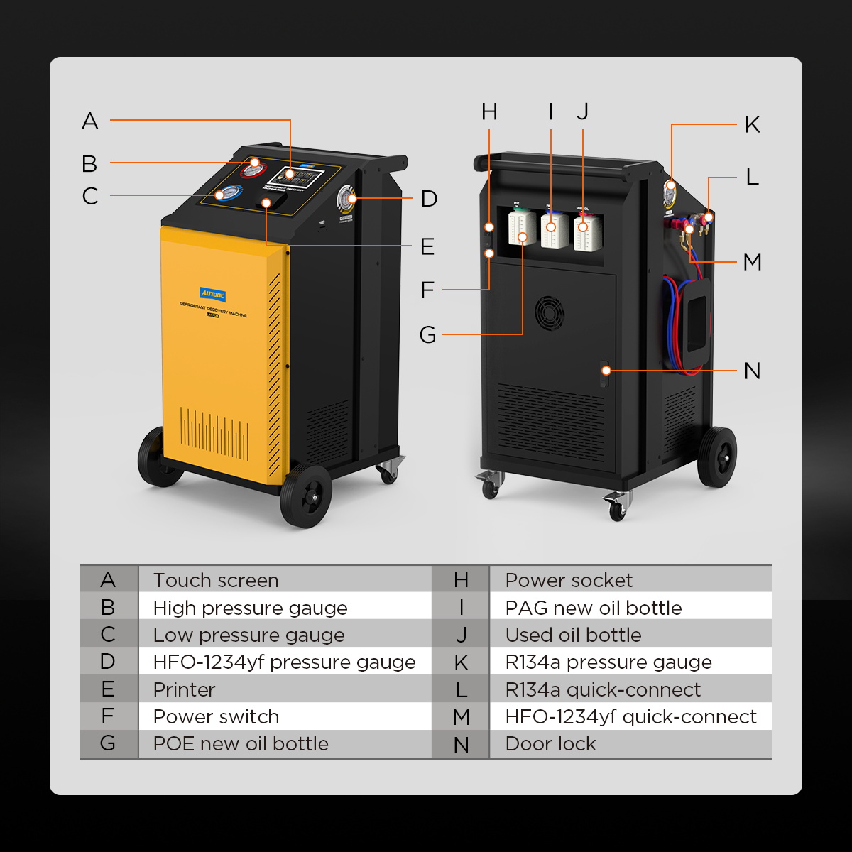
Understand the LM708 layout
At the front, identify the touchscreen, printer, high- and low-side gauges, dedicated R134a gauge and dedicated HFO-1234yf gauge. At the service-connection area, identify all four quick connectors rather than relying on red and blue color alone: R134a high and low, plus HFO-1234yf high and low.
At the rear, identify the PAG new-oil bottle, POE new-oil bottle and used-oil bottle. Each refrigerant tank and each of the three oil bottles has its own weighing function. The touchscreen should show the selected refrigerant and oil context at the top of the working screen; treat that label as a required cross-check before every transfer.
The quick-coupler valve illustration in some translated instructions can be read incorrectly. Follow the physical arrow marked OPEN, the current touchscreen illustration and the observed valve state. Do not depend on a remembered clockwise or counterclockwise rule.
LM708 step-by-step operating procedure
Step 1: Define the exact service job
Write down the vehicle identification, refrigerant label, specified charge mass and tolerance, oil specification, oil-replacement rule, high- and low-side port locations, required evacuation target, leak-test method and final operating test. Decide whether the job is recovery only, recovery followed by repair, evacuation and recharge, or a fully verified automatic sequence.
If the vehicle label and current service data disagree, stop and resolve the discrepancy before connecting. Do not use a charge value simply because it appears in an onboard database.
Completion check: Every quantity, material and pass/fail condition is traceable to the exact vehicle.
Step 2: Prepare the bay, vehicle and power supply
Park and restrain the vehicle in a ventilated work area. Keep the engine and A/C off during setup. Position the LM708 upright on a level surface, lock its caster and leave enough room for ventilation, rear access and safe hose routing. Check that the supply voltage and frequency match the rating plate before connecting power.
Route the cord and hoses where they cannot be crushed, pulled across an aisle or contact belts, fans, exhaust parts or high-voltage components. Keep emergency access clear and do not leave a powered machine unattended.
Completion check: The machine is stable, the vehicle is secure, PPE and ventilation are ready, and no cable or hose enters a hazard zone.
Step 3: Inspect the delivered machine and accessories
Inventory the LM708, red and blue hoses, both R134a quick connectors, both HFO-1234yf quick connectors, power cable and any supplied adapters. Inspect hose ratings and condition, coupler seals and valves, threads, strain reliefs, bottle connections, gauges, printer, vents and enclosure.
The R134a and HFO-1234yf connectors must remain dedicated to their marked circuits. Never force an adapter to make the wrong connector fit, and never exchange parts between circuits merely because their colors match.
Completion check: Every part is clean, undamaged, correctly rated and positively assigned to one refrigerant circuit.
Step 4: Release the scale transport lock before first use
Open the rear access only with the machine de-energized. Locate the electronic-scale protective device shown in the current LM708 manual and release its locking screw from the scale-tray locking hole. This is a first-use or post-transport preparation step; a locked or mechanically loaded tray cannot weigh refrigerant correctly.
Confirm both internal tanks remain seated exactly on their load platforms and do not contact the cabinet or loose hardware. Do not recalibrate a scale to hide a mechanical obstruction or unreleased shipping lock.
Completion check: The current manual’s transport protection is released, both tank platforms move as designed and no object loads a weighing path.
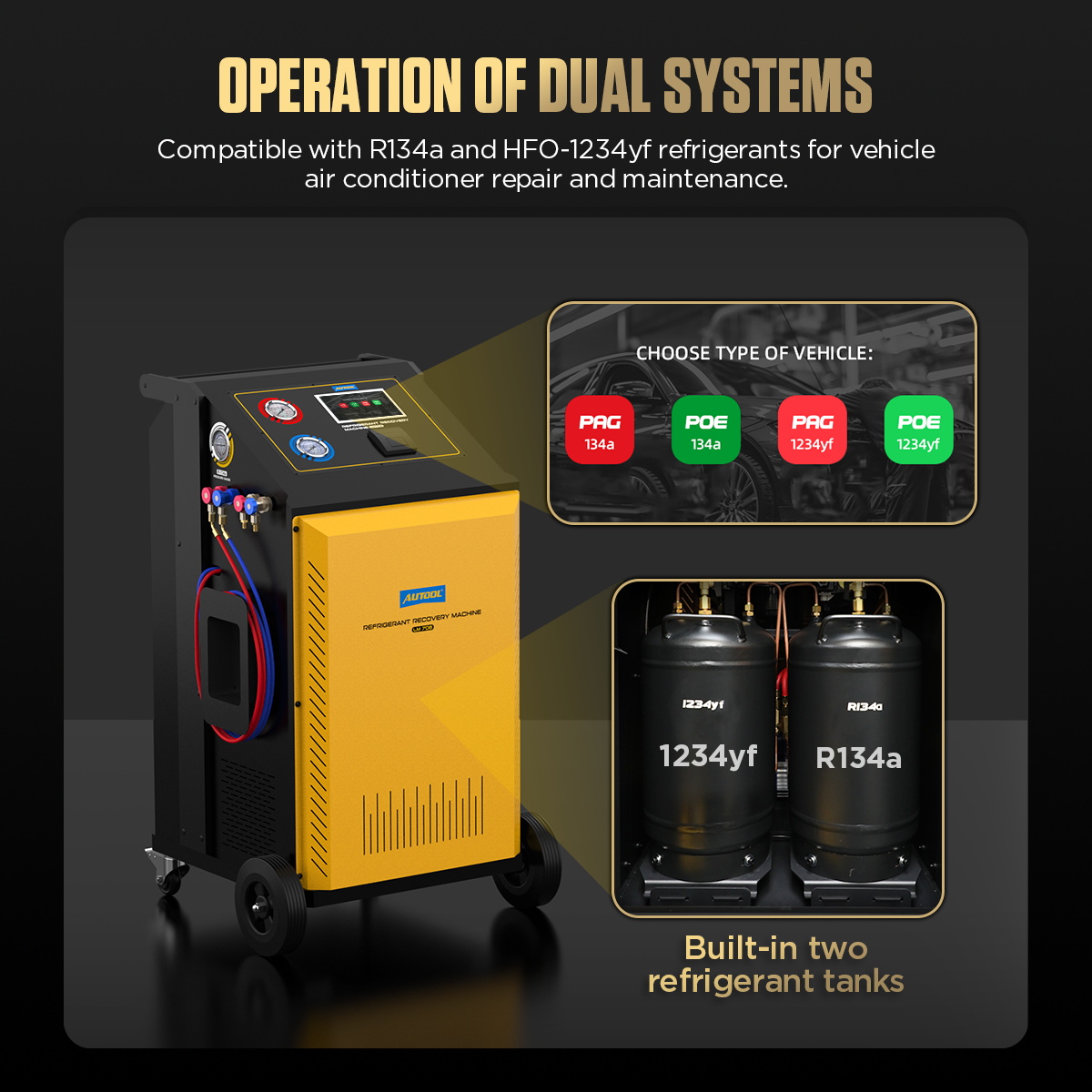
Step 5: Select the correct refrigerant circuit
Verify the vehicle label and, when required, test the refrigerant with an approved identifier before it reaches the machine. Start the LM708 and select either R134a or HFO-1234yf. Confirm that the touchscreen header, tank status, pressure indication and available connectors all match that choice.
When changing the selected refrigerant, allow the LM708 to complete its prompted internal hose-cleaning sequence. Do not interrupt it. Cleaning manages the machine’s internal path; it cannot identify the vehicle charge or correct mixed or contaminated refrigerant.
Stop if the screen label, physical connector set, source refrigerant or vehicle label does not agree.
Completion check: One verified refrigerant is selected and the matching tank, screen and dedicated connector set agree.
Step 6: Fill the selected internal tank when required
The machine ships without service refrigerant. Fill only the selected circuit, using a certified source cylinder containing verified refrigerant of that same type. Open Maintenance, choose Tank Filling and enter only the quantity permitted by the current screen, current manual revision, physical tank label and local cylinder rules.
Connect the selected circuit’s designated fill hose to the source cylinder exactly as the current screen illustrates. Keep the cylinder stable in the orientation required for the transfer. Follow the prompts to evacuate the transfer hose before opening the source-cylinder valve. Begin filling, monitor the actual transferred mass, and remain with the machine.
At the preset amount, close the source-cylinder valve when prompted. Let the LM708 recover the refrigerant remaining in the transfer hose before disconnecting. Never disable overfill protection, move a tank on its scale, substitute an uncertified container or turn a disputed marketing capacity into a fill target.
Completion check: The selected tank is inside the delivered unit’s permitted working window, the source valve is closed and hose refrigerant has been recovered rather than vented.
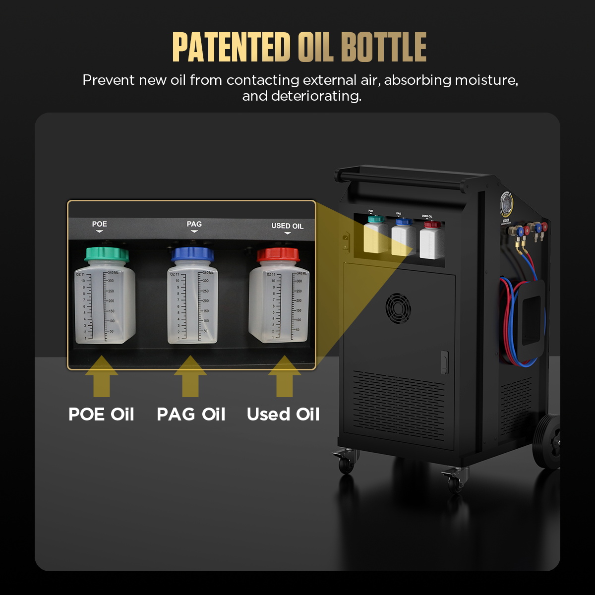
Step 7: Prepare the oil bottles and job record
Empty the used-oil bottle into the approved waste stream before recovery, then reinstall it securely. Confirm that each new-oil bottle is clean, closed and labeled with the exact chemistry it contains. Do not top one oil with another or infer oil type solely from refrigerant or vehicle propulsion type.
For a hybrid or electric vehicle, obtain the exact high-voltage compressor-oil specification and contamination-control procedure. Conductive PAG contamination can compromise an electrically driven compressor system that requires a different insulating oil. Use the LM708 oil path only when the current vehicle procedure approves its chemistry, bottle segregation and injection method.
Record the starting tank readings, PAG and POE bottle readings, used-oil reading, filter life, vacuum-pump-oil status and any machine warning.
Completion check: Removed oil can be measured for this job, new oils cannot be confused and all starting values are recorded.
Step 8: Confirm charge data instead of trusting one lookup
Search the onboard vehicle database if it helps locate a candidate value, but compare that result with the under-hood label and current service information for the exact market, engine, model year and A/C option. Check whether the displayed unit is grams, kilograms, ounces or pounds before accepting any value.
The database does not override a revised label, service bulletin or replacement-component instruction. It also does not decide the oil quantity after a component repair.
Completion check: Charge mass, units and oil rule are independently verified and written on the job record.
Step 9: Connect the selected high and low sides
With the engine and A/C off, make sure both selected quick-coupler valves are closed. Connect blue to the verified low-side service port and red to the verified high-side port. Trace both hoses back to the connector set for the selected refrigerant; never connect one hose from each refrigerant family.
Seat each connector without force, lightly tug it to confirm engagement and route the hoses away from movement and heat. Open the coupler valves only in the direction shown by their OPEN arrows and the current on-screen illustration.
Stop if a port cannot be positively identified, a coupler resists, a seal leaks, the fittings do not belong to the selected refrigerant, or either hose can move into danger.
Completion check: Both service paths are secure, correctly identified, from one refrigerant circuit and safely routed.
Step 10: Use the A/C pressure check as a condition snapshot
Select A/C Pressure Check only after the selected circuit and connections are verified. Follow the prompts for valve state and any required vehicle operating condition. Observe both gauges and record the exact ambient, vehicle and A/C state with the readings.
Pressure is not a substitute for refrigerant identification or charge-by-mass. Static pressure alone cannot prove charge quantity, and running pressures without temperature, airflow and control context can mislead diagnosis.
When the check is complete, let the LM708 recover refrigerant remaining in the hose path as prompted.
Completion check: The readings have a defined test condition and no diagnosis rests on pressure alone.
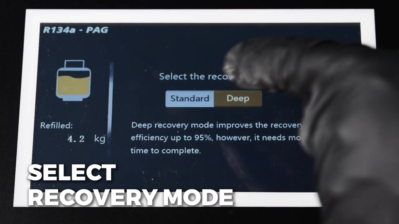
Step 11: Recover refrigerant and verify completion
Select Manual and Recovery, then choose Standard or Deep recovery according to the current LM708 prompt and service plan. Deep recovery is intended to improve recovery completeness but requires more time. Confirm the selected refrigerant, used-oil bottle readiness, tank working window and hose valves before starting.
Keep the engine and A/C off. Watch the machine status, gauges and recovered mass. Do not disturb the internal tanks or bottle scales during transfer. When the program reports completion, record recovered refrigerant and discharged oil.
Allow the system the pressure-rise observation required by the vehicle and shop procedure. If pressure returns, repeat the permitted recovery step and investigate trapped refrigerant, temperature effects or leakage. An automatic stop is not by itself proof that the circuit is ready to open.
Completion check: Recovery remains complete through the defined observation, and both recovered refrigerant and oil are recorded.
Step 12: Measure removed oil before choosing replacement oil
Let the used-oil bottle settle and record the amount and condition of oil removed. Determine replacement chemistry and quantity from the exact vehicle procedure and the components repaired. Do not automatically inject a one-for-one volume if the OEM method calls for a different calculation.
Keep recovered oil out of the new-oil bottles. If oil identity is uncertain, if the wrong new-oil bottle was connected, or if PAG may have entered a POE-controlled high-voltage path, stop and apply the approved contamination procedure.
Completion check: Oil chemistry, amount and injection method are documented for the exact compressor system.
Step 13: Repair and leak-test before evacuation
If the system lost charge or was opened, complete the mechanical repair first. Replace required seals and service-port cores, torque fittings to specification and use only the vehicle-approved pressure-test medium, regulator, limit and method. Never use compressed air or oxygen.
A pressure-rise observation after recovery, the LM708 vacuum decay screen and an electronic leak detector answer different questions. Use the complete required method to locate and confirm the repair; do not proceed merely because one short test appears stable.
Completion check: The circuit is correctly assembled and has passed the specified pre-evacuation checks.
Step 14: Evacuate to a defined acceptance gate
Select Vacuum in Manual mode. Enter the evacuation time required by the exact vehicle and workshop procedure, then choose the pressure-decay check and its duration when appropriate. Follow every valve prompt and keep the selected connections undisturbed.
Elapsed time alone does not prove that the system is dry and tight. If the procedure requires an absolute micron target and a standing decay limit, use the specified instrument at the specified location. Stop for an unexplained pressure rise, a leak message, abnormal pump noise, smoke or oil-backflow symptom instead of extending time blindly.
Completion check: The system meets both the required evacuation condition and the defined hold or decay criterion.
Step 15: Choose the oil decision and charge path
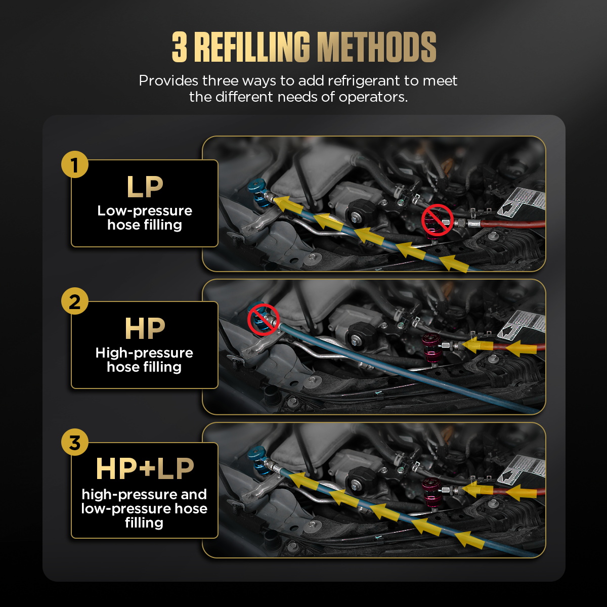
Before entering Charge, confirm whether oil is to be added, which bottle is allowed and the exact amount. Then select LP, HP or HP+LP only when that path is permitted by the vehicle procedure and current LM708 prompt.
These paths are not interchangeable shortcuts. High-side charging can create a liquid-refrigerant hazard if used in the wrong operating state, while low-side charging into a running system requires a controlled procedure that protects the compressor and operator. Do not improvise a port choice from a generic online sequence.
Completion check: Oil decision, charge path, required valve state and vehicle operating state are explicitly approved for this job.
Step 16: Enter the exact charge mass and start refilling
Enter the confirmed refrigerant mass and recheck the units. Verify the touchscreen header still shows the correct refrigerant and oil context, then compare the complete summary with the job record. Start the charge and monitor preset versus actual mass, tank status, gauges and prompts.
Keep the engine off during the principal measured transfer unless the current screen and exact vehicle procedure direct a controlled running step. Remain with the machine and stop on an unstable scale, incorrect circuit label, overfill warning, unexpected pressure or delivered-mass mismatch.
Completion check: The recorded delivered mass equals the vehicle specification within the approved service tolerance.
Step 17: Use Automatic mode only after validating every stage
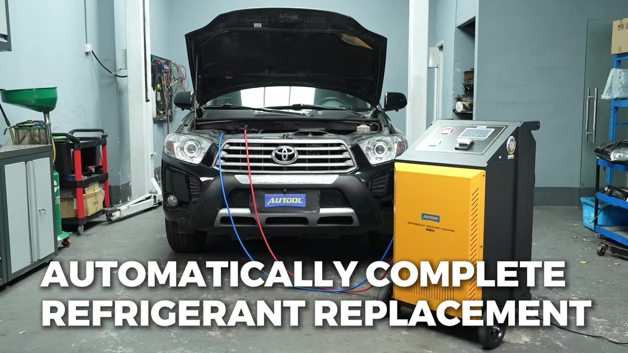
Automatic mode can sequence recovery, evacuation, leak checking, oil addition and charging after parameters are preset. Before starting it, repeat the same gates used in Manual mode: verify refrigerant identity and circuit, empty the used-oil bottle, confirm the tank window, select the recovery method, set the required vacuum and leak-check criteria, decide oil chemistry and quantity, enter the exact charge mass and choose the permitted charge path.
Read the full summary before confirmation. Automation controls the sequence; it does not repair a leak, correct bad data, detect mixed refrigerant or make an uncertain oil choice safe. Stay with the machine and respond to each valve or hose prompt.
Completion check: Every automated-stage input has been independently verified and the final report matches the planned job.
Step 18: Finish the cycle and disconnect without venting
Follow the current screen through pressure balancing and recovery of refrigerant remaining in the hoses. If the exact procedure calls for a brief engine-and-A/C-on step, keep hands, clothing and hoses clear of moving and hot parts and perform only that defined step.
Close the quick-coupler valves when prompted, isolate the service paths and let the LM708 clear the trapped hose refrigerant. Remove the connectors in the specified order, inspect the ports for leakage and reinstall both service-port caps to the vehicle-specified condition.
Completion check: No refrigerant was intentionally released, both service ports are sealed and the machine reports a completed transfer.
Step 19: Verify A/C operation and print the record
Run the vehicle under the exact final-test condition. Record ambient temperature, vent temperature, high- and low-side pressure behavior, compressor request and response, fan operation and any scan data required by the vehicle procedure. A correct charge mass does not by itself prove airflow, heat-exchanger, control or compressor performance.
Review the LM708 result screen and print or save the service data. Add vehicle identity, refrigerant and oil information, recovered and charged amounts, evacuation and leak-test results, final readings, technician and date.
Completion check: The final result meets the exact acceptance window and the job remains traceable.
Step 20: Complete maintenance and storage
Review filter and vacuum-pump-oil counters after the job. The current LM708 information calls for filter-drier replacement after 100 kg of processed refrigerant. Reset a filter counter with password 8609 only after the correct filter has actually been replaced and the maintenance sequence, recovery and equipment leak check have passed.
Replace vacuum-pump oil through the Maintenance program when prompted or sooner if its level or condition is unacceptable. Scale calibration, internal-tank cleaning, manual exhaust, pressure-system repair and electrical work are specialist procedures; de-energize the machine and use qualified service rather than bypassing a fault.
Clean the exterior, inspect hoses and couplers, secure the oil bottles and store the LM708 upright in a dry, ventilated area. Keep both refrigerant circuits labeled and capped for the next job.
Completion check: Counters represent real maintenance, consumables are serviceable and both circuits are clean, closed and identifiable.
LM708 control gates
| Gate | Pass condition | Stop when |
|---|---|---|
| Machine identity | Current dual-system LM708, rating plate and procedure agree | An older single-circuit panel or unmatched manual is present |
| Refrigerant | Vehicle, identifier, selected screen, tank and couplers agree on R134a or HFO-1234yf | Refrigerant is unknown, mixed or connected to the other circuit |
| Weighing | Transport lock is released; tanks and bottles are stable on their scales | A tank is shifted, a scale is unstable or overfill protection is unavailable |
| Oil | Exact chemistry, quantity and injection method are approved | PAG/POE identity or high-voltage compatibility is uncertain |
| Repair and evacuation | Approved leak test, evacuation target and hold criterion pass | A short vacuum or timer is the only evidence |
| Charge | Exact mass, units, circuit and LP/HP path are confirmed | Database or generic pressure replaces vehicle data |
| Finish | Hose refrigerant is recovered and both caps are restored | A connection remains pressurized or venting would be required |
Common LM708 problems
The selected refrigerant does not match the connected hoses
Do not continue. Close and isolate the connections without venting, then trace every hose and coupler to its marked circuit. If refrigerant may have crossed circuits, quarantine the machine and apply the approved contamination and cleaning procedure before another vehicle is connected.
The tank or bottle amount does not change
Stop the transfer. Check that the scale transport lock is released, the tank or bottle is seated freely on its load platform, no hose or cabinet part is applying force and the correct selected circuit is displayed. Do not recalibrate merely to force a plausible reading.
Recovery will not finish
Cold refrigerant can lengthen recovery. Check the selected tank window, coupler state, hose restrictions and vehicle leakage, then follow the displayed fault path. A compressor, sensor, valve or circuit fault requires qualified machine service.
Vacuum will not hold
Confirm all external connections and the completed repair, then inspect vacuum-pump oil level and condition. Use the required absolute vacuum and decay method. Extending the timer cannot repair a leak, remove an obstruction or correct degraded pump oil.
Charging is slow or will not start
Recheck selected refrigerant, available tank amount, charge units, LP/HP path, coupler valves and displayed fault. Never heat a tank with flame, bypass pressure protection, falsify a scale value or switch refrigerant circuits to force charging.
AUTOOL LM708 FAQ
Can LM708 service R134a and HFO-1234yf at the same time?
It contains independent systems for both refrigerants, but one verified circuit should be selected and controlled for each vehicle job. Do not run mixed connections or parallel service paths.
Does internal hose cleaning identify or purify unknown refrigerant?
No. It prepares the machine path when changing the selected circuit. Unknown, mixed or contaminated vehicle refrigerant must be identified and handled by the approved process before connection.
Can I use the onboard database as the final charge specification?
Use it as a lookup aid. Confirm the exact mass and units against the vehicle label and current service information before starting a charge.
Does LM708 automatically choose PAG or POE oil?
No. The technician must verify oil chemistry, amount and contamination-control method for the exact compressor. This is especially important on hybrid and electric vehicles.
Is the built-in vacuum leak check enough to prove a repair?
Not in every procedure. A vacuum-decay result does not locate a leak and may not replace an approved pressure test, tracer method or specified absolute-micron test.
When should password 8609 be used?
Use it only after the correct filter drier has actually been replaced and the current maintenance procedure has passed. Never reset the counter to silence a service warning.
The reliable LM708 workflow
Identify the refrigerant and exact vehicle data, prepare the bay and weighing system, select one dedicated circuit, fill only its tank when required, segregate PAG and POE, connect the matching high and low sides, recover and verify pressure stability, account for oil, repair and leak-test, evacuate to a defined gate, charge the exact mass through the approved path, recover hose refrigerant, verify vehicle performance and preserve the record. Automatic mode is reliable only after each of those decisions is already correct.


Comments 0
Questions, fixes, and real-world diagnostic notes from readers.
Be the first to share a diagnostic result or ask a follow-up question.