
How to Use the AUTOOL LM707 Refrigerant Recovery Machine

Use the current AUTOOL LM707 by confirming that the vehicle contains R134a, matching the machine in front of you to the current 5-inch-control-panel version, checking the internal tank and maintenance status, and connecting the red and blue service hoses with the engine and A/C off. Recover first, allow the required pressure-rise check, account for removed oil, evacuate for the vehicle-specified time and acceptance test, then charge the exact R134a mass. Use Auto mode only after every parameter and oil decision has been verified individually.
The LM707 automates refrigerant movement; it does not identify an unknown refrigerant, choose a charge mass, repair a leak or decide whether a compressor needs oil. Those decisions still come from the vehicle label, current service information, refrigerant-identification controls and the technician.
Updated August 27, 2026.
In this guide
What the current LM707 does
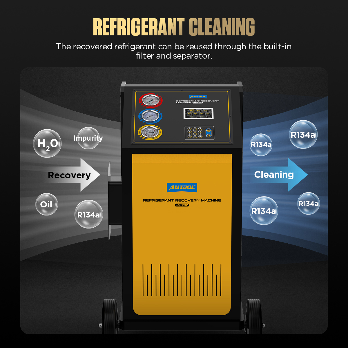
The current AUTOOL LM707 is an R134a-only recovery, recycling, evacuation and measured-recharge station. Its present product configuration uses a 5-inch display with a keypad, separate high- and low-side gauges, a tank-pressure gauge, a 12 kg internal tank, new- and used-oil bottles and automatic recovery, vacuum and filling functions.
LM707 hardware has changed over time. Older LM707 material shows a 7-inch touchscreen, refrigerant selection, a database and other controls that are not part of the current R134a-only configuration. Do not transfer an older screen sequence, tank target or refrigerant option to the current machine merely because both carry the LM707 name.
Before you connect
Open the AUTOOL manual download center and obtain the manual that matches the control panel, rating plate and serial generation in front of you. Also obtain the vehicle refrigerant label and exact service procedure, including refrigerant type and mass, oil type and quantity rule, service-port layout, evacuation target, leak-test method and final performance test.
This equipment handles liquid refrigerant, pressure and mains electricity. Use it only if you are trained and authorized for refrigerant service in your jurisdiction. Wear safety glasses and refrigerant-compatible gloves, provide ventilation, keep ignition sources and hot surfaces away, and use the correct grounded supply. Never use compressed air or oxygen to pressure-test the machine or vehicle A/C system.
Stop: Do not begin if the refrigerant is unknown or contaminated, the vehicle is not labeled for R134a, the machine configuration does not match the current procedure, the internal cylinder or scale is disturbed, a hose or coupler is damaged, an overfill safeguard is disabled, or the required charge and oil data are unavailable.
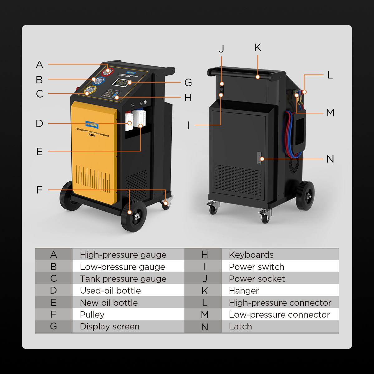
Understand the current LM707 layout
The front panel places the red high-side gauge above the blue low-side gauge and the yellow tank-pressure gauge below them. The current screen presents Recovery, Vacuum, Charge, Tank Fill, refrigerant-circuit cleaning, Auto Mode and Settings functions; the keypad is used to select a function, enter values, confirm or return. The service ports, oil bottles, power switch, power inlet, fuse, storage hardware and internal-cylinder access must match the current structure diagram before operation.
LM707 step-by-step operating procedure
Step 1: Define the exact service job
Write down the vehicle, refrigerant label, specified R134a mass, oil specification, permitted oil-replacement method, service-port arrangement, evacuation time and acceptance method. Decide whether the job requires recovery only, recovery plus repair, evacuation and recharge, or a fully verified automatic sequence.
Completion check: Every quantity and pass/fail criterion is traceable to the exact vehicle procedure.
Step 2: Make the work area and power supply safe
Park the vehicle securely in a ventilated bay. Keep the engine and A/C off unless a later vehicle procedure explicitly calls for operation. Route the power cord where it cannot be crushed or pulled, confirm that supply voltage matches the machine plate, and keep gasoline, flame, heaters and sparks away.
Completion check: PPE, ventilation, vehicle restraint, electrical supply and emergency access are ready.
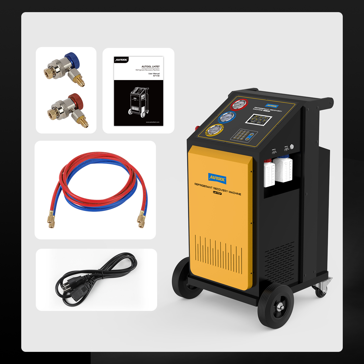
Step 3: Match the delivered kit
Inventory the current LM707, red and blue service hoses, high- and low-side quick couplers, power cable, manual and included adapters. Inspect hose dates and ratings, seals, threads, coupler valves, strain reliefs and bottle connections. Color helps orientation but never replaces port labels and end-to-end tracing.
Completion check: Every part is compatible, clean, undamaged and rated for R134a service.
Step 4: Inspect the machine before startup
Check the three gauges, display, keypad, power inlet, fuse holder, oil bottles, tank area, wheels, vents and enclosure. Confirm the internal cylinder remains correctly seated on its weighing platform. Before first use or after transport, verify any shipping or load-cell locks named by the current unit instructions; do not guess their location from an older LM707 manual.
Stop: A shifted cylinder, unreleased shipping lock, damaged scale, loose bottle, contaminated hose or abnormal gauge reading can corrupt the measured transfer.
Completion check: The machine is stable, unobstructed and ready to weigh refrigerant correctly.

Step 5: Start the machine and verify the current interface
Power on and compare the screen and keypad with the current 5-inch-panel reference. Read all filter, vacuum-pump-oil, tank-level and fault messages before selecting a function. Set language and units only through the current Settings menu; do not enter a legacy service password or calibration menu as part of normal operation.
Completion check: The screen is the expected current interface and no maintenance or fault prompt is being bypassed.
Step 6: Verify R134a and internal-tank readiness
Confirm the vehicle label states R134a. If refrigerant identity is uncertain, isolate the vehicle and use the approved identification process before connecting it to the LM707. Check the displayed internal-tank amount and pressure against current machine instructions. Never defeat overfill protection, alter a pressure-reducing device or substitute a tank target taken from older LM707 material.
If the current unit requires a non-condensable-gas check or purge, follow its own label, pressure-temperature chart and prompt. A purge control is not a shortcut for clearing service hoses or intentionally venting refrigerant.
Completion check: Only verified R134a will enter the current LM707, and its internal cylinder is inside the permitted working window.
Step 7: Prepare the oil bottles and record the baseline
Empty the used-oil bottle before recovery and reinstall it securely. Confirm the new-oil bottle contains only the exact compatible oil approved for this vehicle and service method; keep different oils and moisture-sensitive electric-compressor oils segregated. Record the internal-tank reading, filter life, pump-oil status and both bottle levels.
Completion check: The used-oil bottle can show this job’s recovered amount and no oil type can be confused.
Step 8: Connect the high and low sides
With the engine and A/C off, close both quick-coupler valves. Connect blue to the verified low-side service port and red to the verified high-side port, then tug each connection lightly. Trace each hose to the matching LM707 port, route it away from fans, belts, exhaust parts and electrical hazards, and open the couplers only in the order required by the current on-screen procedure.
Stop: If a coupler resists, a port cannot be positively identified, a seal leaks or a hose can move into danger, close, isolate and correct the setup.
Completion check: Both paths are secure, correctly identified and safely routed.
Step 9: Run Recovery and perform the pressure-rise check
Select Recovery, confirm the used-oil bottle is empty and follow the current screen prompts. Keep the engine and A/C off. Watch the gauges and machine status; do not disconnect or disturb the weighing platform during transfer.
When recovery stops, leave the machine connected for at least three minutes, longer in cold conditions or when the vehicle procedure requires it. If vehicle pressure rises, repeat recovery and investigate the reason. Do not treat the first automatic stop as proof that all refrigerant has left trapped volumes.
Completion check: Recovery remains complete through the defined pressure-rise observation and the recovered mass is recorded.
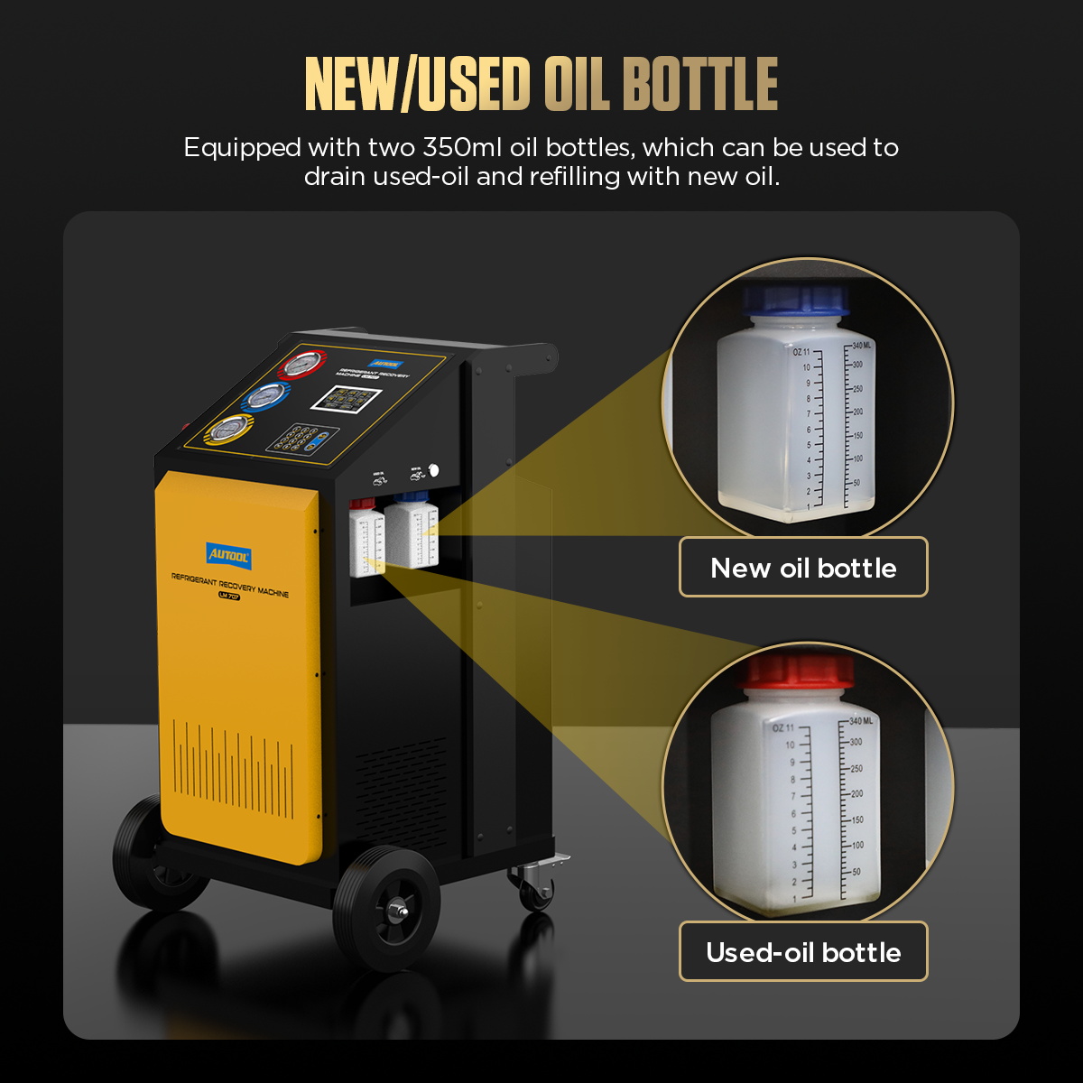
Step 10: Account for recovered oil before adding oil
Allow the used-oil bottle to settle and record the amount removed. Inspect its condition without mixing it back into the system. Determine any replacement quantity from the vehicle procedure and actual repair—not from a generic one-for-one assumption.
For a hybrid or electric vehicle with an electrically driven compressor, do not use the LM707 oil path unless current exact documentation explicitly approves the machine, oil chemistry and contamination-control method for that vehicle. Conductive PAG contamination can damage a high-voltage system.
Completion check: Oil type, amount and injection method are documented and compatible with the exact compressor system.
Step 11: Repair and leak-test before evacuation
If the system was opened or a leak caused the service, complete the repair and use the vehicle-approved leak-test method and medium. Never use compressed air or oxygen. A recovery pressure-rise check, short vacuum or automatic cycle does not locate a leak or certify repair quality.
Completion check: The circuit is correctly assembled and has passed the specified pre-evacuation checks.
Step 12: Run Vacuum to the specified acceptance gate
Select Vacuum, enter the time required by vehicle and workshop procedure, then start. Keep hoses, couplers and bottle valves in the exact prompted state. If the procedure requires an absolute micron target and standing decay test, use the specified measurement method at the required location; elapsed time alone is not proof of dryness or tightness.
After evacuation, add oil only by the verified method from Step 10. Stop for a vacuum fault, unexplained pressure rise or oil-backflow symptom instead of extending time blindly.
Completion check: The system meets both the required evacuation condition and the defined hold or decay test.
Step 13: Enter the exact charge mass and charge R134a
Select Charge and enter the mass from the vehicle label or exact service data. Recheck units before confirmation. Use only the connection path and valve sequence shown by the current LM707 and vehicle procedure; do not copy high-side, low-side or dual-side choices from the older 7-inch interface.
Keep the engine off during the principal measured charge unless the current screen and vehicle procedure explicitly direct a controlled final step. Monitor tank status and gauges, and stop on a fault, unstable scale or quantity mismatch.
Completion check: The recorded delivered mass equals the specified R134a charge within the approved service tolerance.
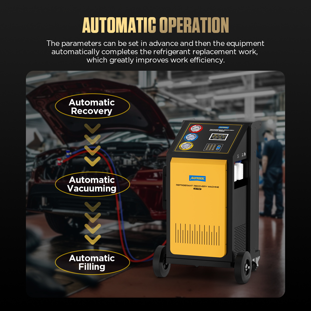
Step 14: Use Auto Mode only after validating each stage
Auto Mode can sequence recovery, vacuum and filling after parameters are preset. Before selecting it, verify R134a identity, empty the used-oil bottle, enter the exact charge mass, set the required vacuum stage and decide the oil method. Review the complete summary on screen before starting.
Automation controls sequence, not judgment. Remain with the machine, watch for prompts and stop if the vehicle state, tank status or result differs from the plan.
Completion check: Every automatic-stage input was independently verified before the cycle began.
Step 15: Finish, clear the hoses and disconnect safely
Follow the current screen’s completion and hose-management prompts. If the exact procedure calls for a brief engine-and-A/C-on step to move remaining hose refrigerant, keep clear of moving and hot parts and perform only that defined step. Close the couplers, isolate the service paths and recover trapped hose refrigerant through the machine rather than venting it.
Remove the couplers in the specified order, inspect for leakage and reinstall both vehicle service-port caps to their required condition.
Completion check: No refrigerant was intentionally released, both caps are restored and the machine shows a completed transfer.
Step 16: Verify vehicle A/C performance
Operate the vehicle only under the specified final test condition. Record ambient temperature, vent temperature, high- and low-side behavior, compressor command, fan operation and any diagnostic data required by the vehicle procedure. A correct charged mass does not by itself prove airflow, control, compressor or heat-exchanger performance.
Completion check: The final result is compared with an exact operating window, not a generic pressure expectation.
Step 17: Maintain the refrigerant and oil circuits
Record the job against the machine counters. The current LM707 information calls for filter service after 100 kg of processed refrigerant, vacuum-pump-oil attention at 600 accumulated minutes and refrigerant-circuit purification about monthly. Replace contaminated or turbid pump oil sooner. Use reset password 8609 only after the corresponding filter service has actually been completed on a current unit.
Keep the exterior, hoses, couplers and bottle area clean and dry. De-energize before opening covers or service areas, and refer internal electrical, pressure and calibration work to qualified personnel.
Completion check: Counters reflect real maintenance, consumables are serviceable and the LM707 is stored ready for the next verified R134a job.
LM707 control gates
| Gate | Pass condition | Stop when |
|---|---|---|
| Machine identity | Current 5-inch R134a-only configuration matches the procedure | Instructions depict a different panel or refrigerant system |
| Refrigerant identity | Vehicle and source refrigerant are verified R134a | Refrigerant is unknown, mixed or mislabeled |
| Weighing | Cylinder and scale are undisturbed and within the current permitted window | A shipping lock, overfill warning or unstable reading appears |
| Oil | Exact oil chemistry, quantity and injection path are approved | Oil identity or electric-compressor compatibility is uncertain |
| Evacuation | Time plus the required absolute/decay criterion passes | Time alone is the only evidence |
| Charge | Exact specified mass and units are confirmed | A generic pressure or older database value replaces vehicle data |
Common LM707 problems
Recovered amount does not change
Stop the process. Check that the vehicle actually contains recoverable refrigerant, the current unit’s scale or shipping lock is in the operating state, the cylinder remains correctly seated and no fault is displayed. Do not recalibrate the load cell merely to force a reading.
Recovery will not finish
Cold refrigerant can lengthen recovery. Check for a vehicle or service-hose leak and follow the current fault path. A compressor, pressure-sensor or internal-valve fault requires qualified equipment service.
Vacuum remains poor
Check connections and the approved leak-test result, then inspect vacuum-pump oil level and condition. Dirty, emulsified or low oil, a restricted inlet, worn seals or an internal leak cannot be corrected by simply adding more time.
Charging is slow or will not start
Check the current internal-tank requirement, hose and coupler valve state, charge units and displayed fault. Never heat the cylinder with a flame, bypass pressure controls or falsify a tank reading.
AUTOOL LM707 FAQ
Does the current LM707 support HFO-1234yf?
No. The current 5-inch LM707 configuration is for R134a only. Older LM707 material showing refrigerant selection is not authority to use HFO-1234yf in the current machine.
Can LM707 identify contaminated refrigerant?
No refrigerant identifier is documented for the current machine. Verify identity before allowing refrigerant into its internal circuit.
Can Auto Mode choose the correct charge and oil amount?
No. The technician must obtain the correct mass, oil rule, evacuation settings and connection method before starting the sequence.
When should the filter counter be reset?
Only after the required filter has actually been replaced and the current maintenance procedure has been completed.
The reliable LM707 workflow
Match the current 5-inch R134a-only machine, verify vehicle data and refrigerant identity, inspect the scale, tank, hoses and oil bottles, connect with the engine and A/C off, recover and observe pressure rise, account for oil, repair and leak-test, evacuate to a defined acceptance gate, charge the exact R134a mass, finish without venting and verify performance under the vehicle-specified condition. Use automation only after every input and boundary is already correct.


Comments 0
Questions, fixes, and real-world diagnostic notes from readers.
Be the first to share a diagnostic result or ask a follow-up question.