
BMW S 1000 RR Multiple Warnings and Rough Running? Inspect Harness Chafe

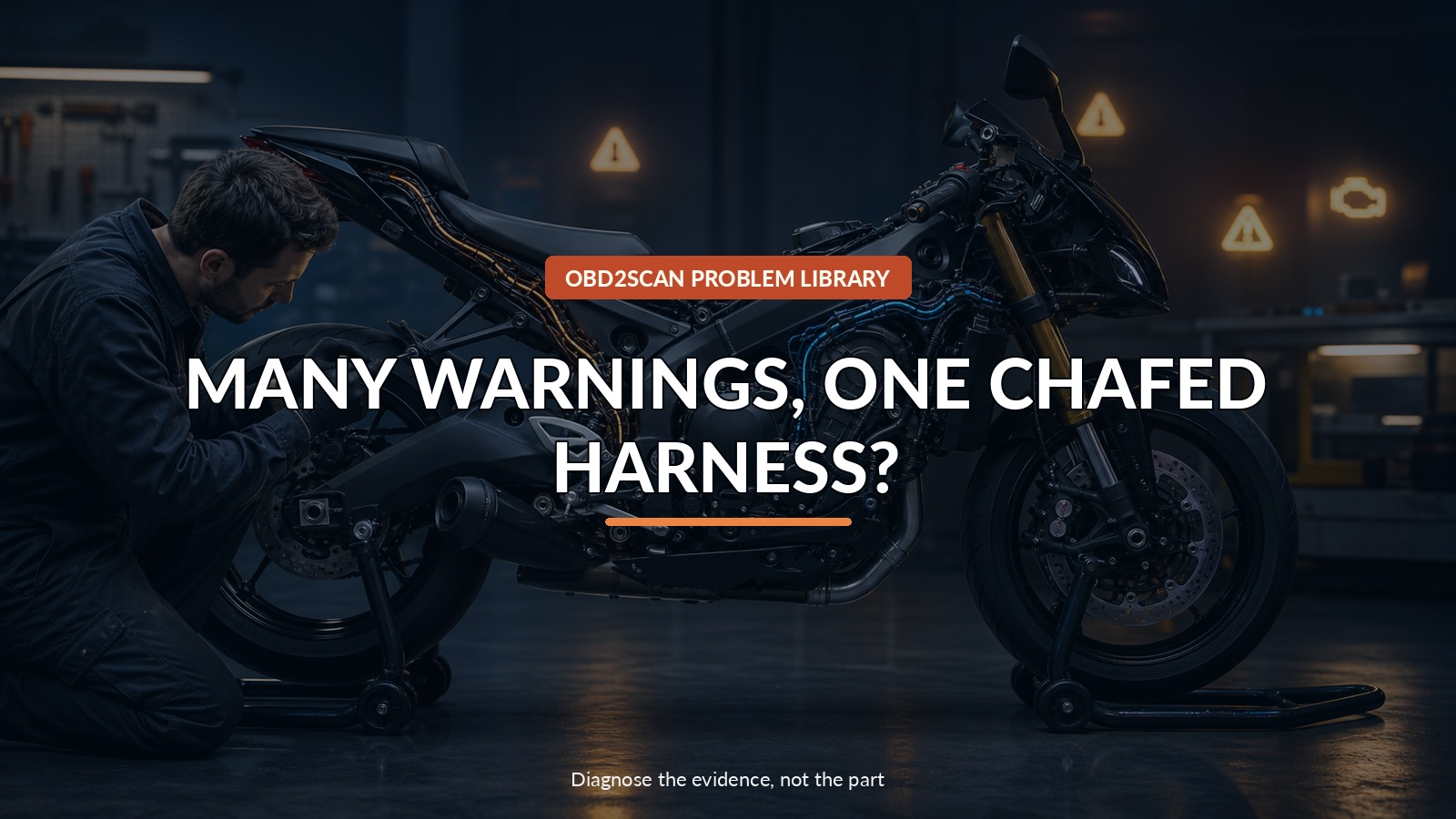
Many Warnings, One Chafed Harness?
When an S 1000 RR or HP4 lights several warnings and runs roughly, the number of messages can make multiple failed modules seem plausible. BMW Motorrad published a simpler physical clue: chafing may affect the engine harness along the left side of the frame or the main harness along the right. Map the affected systems onto those routes before unwrapping or replacing anything.
A motorcycle-specific diagnostic interface can preserve the fault constellation and available live data before intermittent contact disappears. The FXTUL M4-BMW motorcycle diagnostic tool is one route for listed supported BMW models with the correct adapter. It cannot see insulation chafe, guarantee access to every HP4 function, reproduce erased freeze frames, make an unsafe motorcycle rideable, or replace BMW wiring diagrams and pin-level confirmation.
This is a left-versus-right overlay, not a code-reader shopping guide. The scan says which circuits complained; the frame route says where several complaints might meet.
Quick answer: Do not ride; save every module fault, map affected components onto the left engine-harness or right main-harness route, then inspect frame contact points.
In this guide
- Park the motorcycle when warnings cross systems
- Save the fault constellation
- Separate left-side and right-side circuit families
- Reconstruct recent bodywork and accessory changes
- Inspect frame contact points without creating damage
- Match wire color to the affected component
- Repair harnesses to professional standard
- Verify statically before any controlled ride
Park the motorcycle when warnings cross systems
Stop and do not ride with active ABS, DDC/suspension, throttle, engine-control, or charging warnings, or with rough running that limits predictable power. Secure the motorcycle upright on suitable stands in a ventilated work area. Turn off the ignition before close harness inspection and keep hands clear of hot exhaust and cooling fans.
Record the exact sequence: key-on self-check, start, handlebar movement, suspension compression, engine temperature, rpm, vibration, rain, washing, or road bump. Note whether full engine speed is unavailable and whether cycling the ignition changes the symptom. Video the instruments without attempting to reproduce the fault in traffic.
Save the fault constellation
Run a complete vehicle scan with stable battery support appropriate for the motorcycle. Save control unit, fault number, present/not present state, frequency, mileage, freeze frame, and any undervoltage context. Do not clear anything until the physical inspection plan is written.
Group faults by shared supply, ground, CAN connection, sensor family, and harness route. Multiple low-voltage faults may still begin at the battery or charging system. Several unrelated component faults that become current at the same vibration or steering position make a shared harness contact more plausible.
Separate left-side and right-side circuit families
BMW’s service information locates the engine wiring harness on the left frame side and the main wiring harness on the right. Use the exact model wiring diagram to place each faulted component into one route. Do not assume physical side from the component’s name.
| Fault grouping | Physical question | Boundary |
|---|---|---|
| Engine sensors/actuators cluster | Do their wires share the left engine-harness route? | A cluster does not prove one rub point |
| ABS, DDC, lighting, controls cluster | Do feeds/data share the right main-harness route? | Module warning does not prove module failure |
| Both sides plus undervoltage | Are battery, grounds, charging, or CAN common? | Do not unwrap both harnesses first |
| One isolated circuit | Is its connector or local branch damaged? | Bulletin topology may not be the shortest path |
Draw the overlay before moving fairings or cable ties. It focuses inspection and preserves as-found routing.
Reconstruct recent bodywork and accessory changes
Ask what changed: fairing removal, tank lift, track preparation, alarm, heated gear, lighting, GPS, quick-shifter work, battery service, crash repair, or transport tie-down. Photograph accessory taps, nonstandard ties, missing clips, and loom positioned against an edge.
An aftermarket change is a lead, not guilt. A factory harness can chafe, and an accessory can be correctly installed. Correlate the timeline and physical contact with the actual faulted wire colors and circuits.
Inspect frame contact points without creating damage
Follow BMW’s panel-removal and support method. Photograph every clip and tie before cutting or releasing it. Use light and a mirror; do not knife open loom, pierce insulation, or tug connectors to “wake” the fault. Look for polished tape, flattened loom, exposed conductor, green corrosion, heat damage, and a route under tension.
If a controlled wiggle test is specified, monitor the relevant live signal with the engine state and safety conditions defined. Move only one small section at a time. A fault that changes when a broad bundle is shaken identifies an area, not the exact conductor.
Match wire color to the affected component
BMW tells technicians to check whether the damaged wire color and component correspond with the reported symptom. Use the exact connector view and wiring diagram. Confirm the circuit at both ends; color can repeat elsewhere in a harness.
Perform loaded voltage-drop, continuity, insulation, or network tests only with modules isolated as specified. A continuity beep through a few remaining strands does not prove the circuit will carry current or resist vibration. Conversely, visible outer-tape wear without conductor or circuit evidence may be a warning to reroute, not proof of the current fault.
Repair harnesses to professional standard
Motorcycle harness repair must survive vibration, steering movement, heat, moisture, and limited clearances. Follow BMW’s approved splice, conductor, seal, stagger, crimp, insulation, abrasion protection, and routing method. Restore every clip and clearance; do not bury an unsupported household-style splice under tape.
If conductor damage is extensive, connector terminals are overheated, CAN geometry is compromised, or access affects safety systems, use an authorized professional repair. Clearances should be checked through full steering and suspension travel with the motorcycle safely supported and ignition state controlled.
Verify statically before any controlled ride
Reconnect and route everything, restore battery support, then run a complete scan. Perform key-on checks, engine start, gentle harness observation, full steering movement, and approved actuator/static functions before considering a road test. Confirm charging voltage and grounds if undervoltage was part of the constellation.
Only after brake, ABS, throttle, suspension, steering, and engine behavior pass static checks should a trained rider make a controlled low-risk verification. Repeat the original temperature or vibration trigger, then scan again. The repair passes when the relevant faults remain absent and the harness stays clear—not merely when the warning disappears after code clearing.




Comments 0
Questions, fixes, and real-world diagnostic notes from readers.
Be the first to share a diagnostic result or ask a follow-up question.