
GM Truck ABS Activates Below 5 MPH With No Code? Compare the Wheel Signals

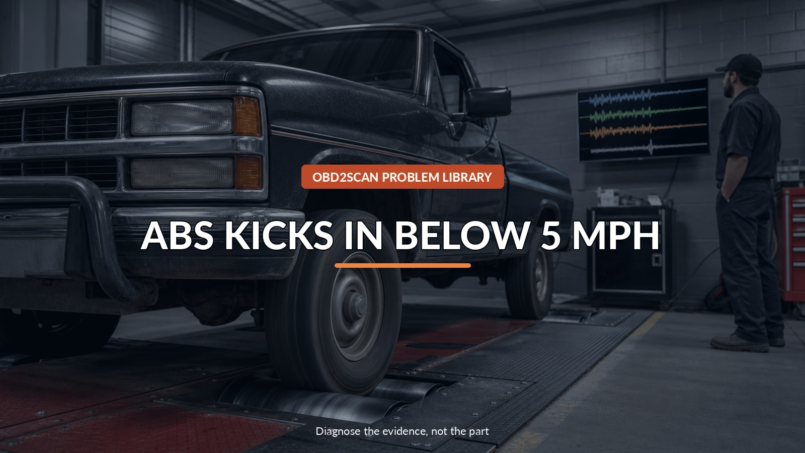
Abs Kicks In Below 5 Mph
When ABS chatters or releases braking just before an older GM truck stops, with no ABS code stored, the event may be a wheel-speed signal falling away too early. GM bulletin 02-05-25-006 describes that pattern on a specific list of 4WD/AWD trucks and utilities. Confirm the truck is actually in scope, compare all wheel signals through the final five mph, and inspect the sensor mounting condition before replacing a hub or controller.
The missing evidence is often dynamic: which signal loses shape first as wheel speed approaches zero. A meter with a compact waveform view can support that comparison at known circuits. The AUTOOL DM303 automotive multimeter/oscilloscope is one route for qualified electrical checks. It cannot make a road test safe, identify a bad hub from one trace, or turn the bulletin’s model-specific voltage check into a universal ABS threshold.
Picture the stop as a slow race: four wheel-speed stories should reach zero together. The first one to vanish can make the controller believe that wheel locked while the truck is still rolling.
Quick answer: On a bulletin-scoped older GM 4WD/AWD truck, compare all wheel-speed signals through the final five mph and inspect the sensor mounting path before replacing parts.
In this guide
Recreate the final five miles per hour
Begin with base-brake safety. Check fluid level by the correct procedure, tire condition and size, wheel security, obvious hub play, brake drag, pedal feel, and warning lamps. If the pedal is soft, braking is severely reduced, a wheel is loose/noisy, or the truck pulls dangerously, do not road-test it.
Ask the driver to describe the event without diagnostic words. Does the pedal pulse? Is there a pump or buzzing sound? Does stopping distance lengthen? Does it happen on dry smooth pavement, only while turning, or only after a bump? At what speed does it begin, and does the ABS lamp remain off?
Use a closed, level test area with a qualified driver and an observer operating the data recorder. Make straight, gentle stops from low speed. Never stare at a scan tool while driving. If activation is violent or unpredictable, stop the test and use bay-safe signal methods.
Confirm the bulletin’s truck list
The GM bulletin names particular 1995–2003 4WD/AWD applications, including selected Chevrolet, GMC, Cadillac, and Oldsmobile truck/utility models. The exact list includes different year ranges and old-style body qualifications. “A 2001 GM truck” is not enough.
Record VIN, model, model year, body generation, drivetrain, ABS option, and hub/sensor service history. Retrieve the current service document for that VIN and compare it with bulletin 02-05-25-006. A two-wheel-drive truck, a later platform, or a different sensor design needs its own specifications and fault tree.
Scan the ABS module even though no warning light remains. Save current and history DTCs, module identity, tire-size/configuration data, and any wheel-speed or voltage records. A no-code complaint makes live evidence more important; it does not prove the controller saw nothing wrong.
Watch four wheel speeds race to zero
Graph all available wheel speeds on the same scale and time base. During a controlled straight stop, look for one channel that drops to zero, spikes, or becomes noisy while the others still report slow rotation. Repeat only enough to establish whether the pattern is consistent.
Then compare the suspect wheel with a known-good side at the sensor or accessible harness point using the correct diagram, terminal method, and measurement mode. Keep the truck securely supported if a wheel must turn off the ground. Never work under a vehicle held only by a jack, and keep clothing and leads away from rotating parts.
A useful trace has context: wheel identity, tire rotation rate, probe location, time base, voltage scale, and comparison channel. A screenshot with no setup record can make a normal amplitude difference look like a fault.
Inspect the signal path and mounting gap
GM’s bulletin describes rust and debris beneath the front wheel-speed sensor increasing the air gap and weakening the signal on its covered hubs. That mechanism earns an inspection only after the vehicle and symptom gates fit.
Inspect connector retention, terminal condition, harness routing, chafing, water entry, and movement with steering/suspension travel. Check hub play, bearing roughness, reluctor condition where accessible, and sensor mounting. Follow the exact removal, cleaning, corrosion protection, fastener, and reassembly procedure; damaging a sensor or sealing surface creates a new fault.
After any sensor-area work, route the harness exactly and confirm it cannot touch the tire, axle, or brake. A restored signal with a pinched wire is not a finished repair.
Keep the old voltage criterion inside its fence
The bulletin includes an AC-voltage check at a specified wheel speed and a 350 mV criterion for its covered configuration. That number belongs to the bulletin’s sensor design, method, meter behavior, and setup. Do not apply it to active digital sensors, newer magnetoresistive bearings, a different rotation speed, or another manufacturer.
Amplitude alone is also incomplete. A circuit may pass a hand-spin number yet drop out under load, steering movement, heat, or the very low speed where the complaint occurs. Conversely, two meters can display different values from the same waveform.
Use the service manual’s sensor type and test method. On active sensors, supply, ground, current modulation, bias voltage, or scan-data interpretation may matter more than an AC output test.
Rule out mechanical and base-brake faults
Do not let a strong signal clue hide ordinary brake problems. A warped or contaminated friction surface, loose suspension, incorrect tire circumference, dragging caliper, master-cylinder issue, or actual wheel slip can change the stop.
Likewise, a noisy bearing can alter the sensor gap, but noise alone does not prove which part should be replaced. Compare mechanical condition, signal behavior, and the prescribed hub/sensor service limits.
The complaint is not solved by pulling the ABS fuse. Disabling a safety system changes braking behavior, creates warnings, and may be illegal or unsafe. Diagnose the activation; do not bypass it.
Verify with controlled low-speed stops
After repair, clear codes only as the service procedure permits and graph all four wheel speeds again. They should decay plausibly to zero without one channel dropping away early. Confirm the ABS lamp performs its normal bulb/self-check and no code returns.
Repeat the same dry, straight low-speed stops in the controlled area, with similar pedal effort. Then inspect the repaired harness and sensor area after steering and suspension movement. The result passes when the original unwanted activation is gone, base braking remains normal, signal evidence explains the change, and no new ABS fault has been introduced.








Comments 0
Questions, fixes, and real-world diagnostic notes from readers.
Be the first to share a diagnostic result or ask a follow-up question.