
How to Use the AUTOOL BT30 and Maintain Battery Tester Accessories

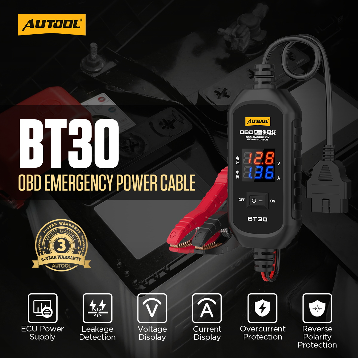
Battery-service accessories have three very different jobs. The AUTOOL BT30 carries limited backup power through the vehicle diagnostic connector during a controlled 12 V battery replacement; the BT960 accessory listing supplies a replacement power cable for a specific tester; and the thermal-paper listing supplies 57 × 30 mm rolls for named printer-equipped battery testers. Treating them as one generic accessory bundle is how wrong cables, wrong paper and unsafe power paths enter a job. This guide separates the three workflows.
Quick answer: For BT30, verify that the vehicle permits OBD memory support, use a fully charged 12 V vehicle battery as the backup source, keep the ignition and accessories off, connect red to positive and black to negative, verify the displayed voltage, then connect the OBD plug and confirm the current display before disconnecting the original battery. Keep the cable protected until the new battery is secure. For replacement tester cables and paper, match the exact tester model, version, connector and dimensions before opening the unit.
In this guide
Match the accessory to one exact task
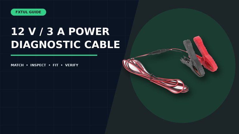
Confirm what the listing includes before planning the job. The BT30 is a complete inline emergency-power cable with clamps, display, OBD plug, switch and built-in fuse. The BT960 listing is explicitly a power-cable accessory only—the tester body is not included. The paper listing contains five thermal rolls only. The following current references should therefore never be substituted for one another:
| Current reference | Included task | Required match |
|---|---|---|
| AUTOOL BT30 ECU emergency power-supply cable | Limited 12 V backup support through the vehicle OBD connector during battery replacement; voltage/current observation. | Vehicle procedure permits the method; current BT30 label/manual and power limits agree. |
| AUTOOL BT960 power-cable accessory | Replacement cable for the named battery-system tester. | Exact BT960 version, connector, polarity and requested part are confirmed before ordering. |
| 57 × 30 mm thermal printer paper | Five replacement rolls for listed printer-equipped testers. | 57 × 30 mm roll, 0.5-inch core and actual printer compartment all match. |
Before first BT30 use, compare the label and supplied booklet with the current AUTOOL manual download center. The retained BT30 manual specifies a 10–14 V operating range, operating current below 7 A and a built-in 3 A fuse. These numbers are not an invitation to power vehicle loads: the vehicle power switch and electrical appliances are to remain off during battery replacement.
How to use the AUTOOL BT30 during battery replacement
Step 1: Confirm the vehicle allows OBD backup power
Read the exact vehicle battery-replacement procedure before connecting BT30. Confirm the diagnostic connector has the required power path and that the manufacturer does not prohibit an external memory saver. Record radio, clock, window, steering and other relearn requirements even when backup power is planned; a fuse opening, loose clamp or vehicle sleep event can still interrupt support.
Check: The vehicle procedure, OBD location and fallback relearn plan are known.
Step 2: Inspect BT30, its fuse and both connection ends
Check clamp insulation, copper jaws, springs, cable jacket, switch, display housing and OBD terminals. Confirm the installed fuse matches the current BT30 label and manual; the retained manual identifies a built-in 3 A fuse. Do not install a larger fuse to stop nuisance opening. Keep the unit out of service if the housing is cracked, a terminal is pushed back or the cable shows heat damage.
Check: The complete BT30 chain is intact, dry and fitted with the specified fuse.
Step 3: Prepare a fully charged 12 V vehicle battery
Use a separate, stable 12 V vehicle battery as the backup source. The current product guidance says not to use a jump starter or power-bank charger in its place. Verify polarity and open-circuit voltage with appropriate equipment. Position the spare battery upright on a stable, insulated surface where the clamps cannot be struck or shorted during removal of the vehicle battery.
Check: The backup source is a fully charged, stable 12 V vehicle battery with clearly identified terminals.
Step 4: Put the vehicle to sleep
Switch the ignition and every accessory off, remove the key and keep hands, tools and chargers from waking the vehicle. The current product page recommends keeping a proximity key at least 3 m away. Wait the time required by exact service information for modules to enter sleep. Do not open doors, operate seats, lights or windows, or run the blower after the backup path is connected.
Check: The vehicle is in its documented low-load state and no planned action will wake a high-current load.
Step 5: Clamp BT30 to the spare battery
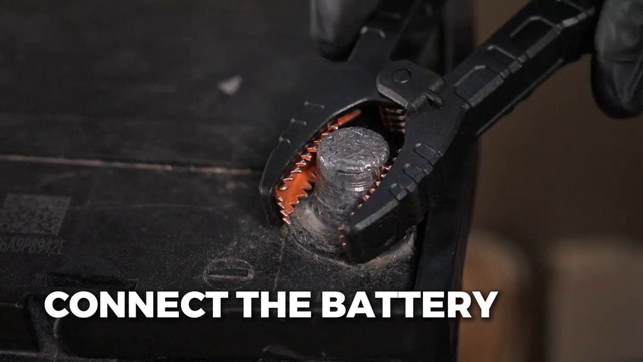
With the BT30 switch in the required off state, connect the red clamp to spare-battery positive and the black clamp to negative. Hold insulated clamp bodies and keep the two jaws separated. The official AUTOOL demonstration shows the clamps secured directly to clean battery terminals. If polarity is uncertain, stop instead of testing the protection circuit.
Check: Both clamps are secure on the correct terminals and cannot touch each other or move.
Step 6: Verify backup voltage before approaching the vehicle port
Switch the unit as directed and read the voltage display. It should agree with the current BT30 operating range and the independently verified spare-battery condition. An alarm or unexpectedly low reading is a reason to stop and check the battery, clamps, fuse and polarity—not to continue in the hope that the vehicle will stabilize the supply.
Check: The displayed voltage is stable, plausible and within the current product limits.
Step 7: Connect the BT30 OBD plug
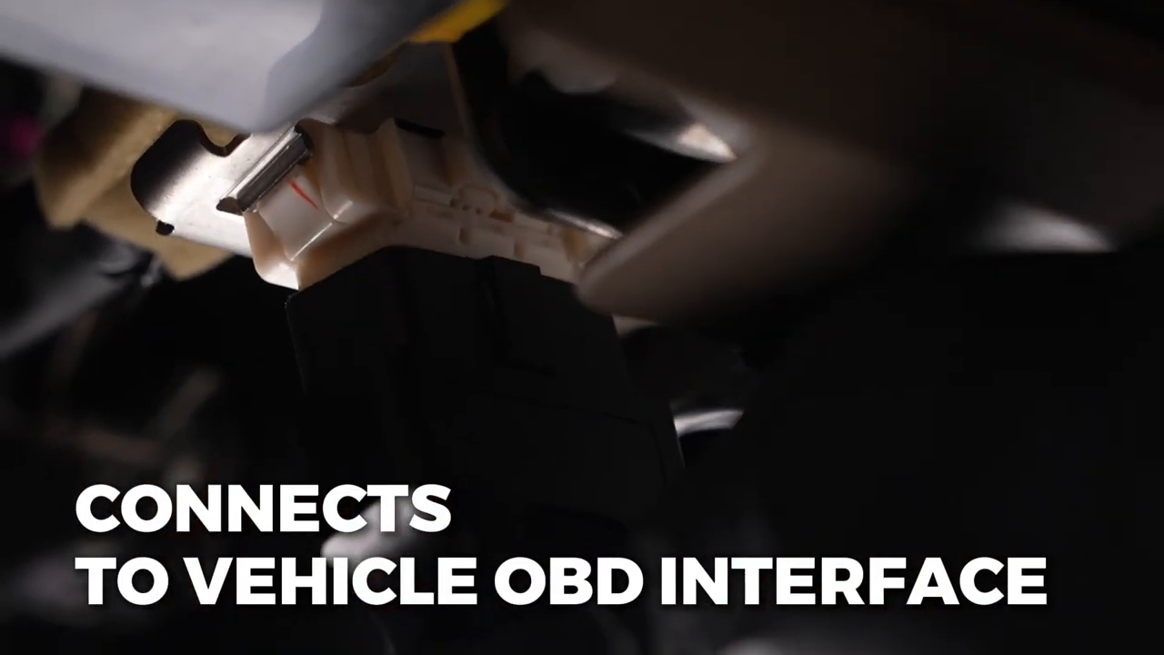
Locate the exact vehicle diagnostic connector, support its mounting and align the BT30 plug by its keying. Seat the housing with normal hand pressure; never pull the vehicle harness toward you or force the plug. The official video shows the plug entering a typical under-dash connector, but connector location and permissible backup-power routing remain vehicle-specific.
Check: The OBD plug is fully seated, the cable has strain relief and the displayed state remains stable.
Step 8: Confirm the current display and protected route
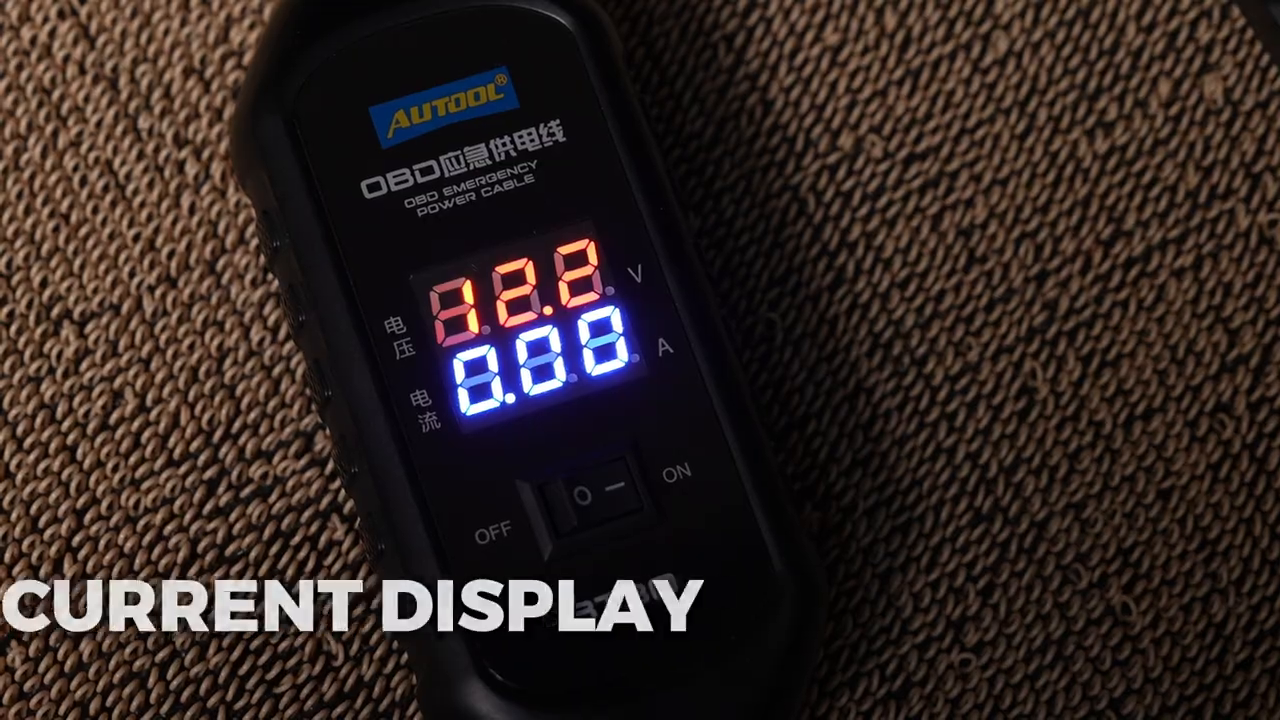
Observe the BT30 current display without waking vehicle systems. A changing value can reflect normal module activity, and one number does not prove parasitic draw. Route the cable and unit away from pedals, steering, seat tracks and the battery-removal path. Support the display so neither it nor the OBD lead hangs from the vehicle connector.
Check: The backup path is mechanically protected and the display does not indicate an immediate overload or loss of supply.
Step 9: Replace the vehicle battery without operating loads
Keep ignition and accessories off. Follow the vehicle procedure to remove the original battery cables, restraint and battery, preventing the positive terminal or tools from contacting ground. Install and secure the correctly specified new battery, then connect and torque its terminals in the required order. The BT30 supports memory power only; it is not a jump lead and must not carry starter, blower, lighting or other operating loads.
Check: The new battery is secure and connected correctly without the backup cable heating, alarming or losing display.
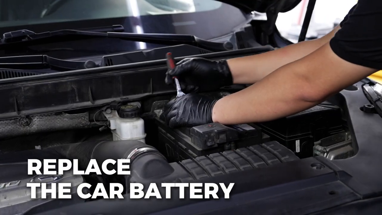
Step 10: Verify the vehicle supply, then remove BT30
Confirm the new battery polarity and stable vehicle voltage before disturbing the backup path. Follow the required order to switch off and remove the BT30 OBD plug by its housing, then remove the spare-battery clamps without allowing them to touch. Start or wake the vehicle only after the cable is completely removed unless the exact procedure says otherwise. Check retained settings and perform any required relearns.
Check: The BT30 is disconnected and stored, the diagnostic connector is intact, and the vehicle operates on the new battery with required settings checked.
Use the BT30 current display carefully
The retained manual also describes an automotive leakage-detection path: connect the spare battery, connect BT30 to the vehicle OBD interface, disconnect the original battery negative terminal, observe current and isolate circuits with the vehicle diagram. That task is more demanding than battery replacement because opening a door, waking a network, removing the wrong fuse or losing the backup connection can change the current and erase evidence.
- Use exact sleep-time and allowable-current information for the vehicle; do not diagnose parasitic draw from a generic threshold alone.
- Record the initial current and time since last activity. Intermittent relay or module activity can make the value fluctuate.
- Use the wiring and fuse allocation for the exact vehicle before removing any fuse. Pulling and reinstalling fuses can wake modules or create new faults.
- Remove one circuit at a time and wait for the vehicle to return to the same state before comparing readings.
- Stop if the BT30 fuse opens, the display resets, a clamp moves, current exceeds the intended support path or service information requires another test method.
Stop: Do not continue if the vehicle cannot enter a stable sleep state, the spare battery is low, polarity is uncertain, BT30 alarms, the displayed voltage collapses, the installed fuse opens, a cable or clamp warms, or the vehicle procedure prohibits OBD backup power. Never bypass or upsize the fuse to keep the job moving.
How to identify and replace a BT960 power cable
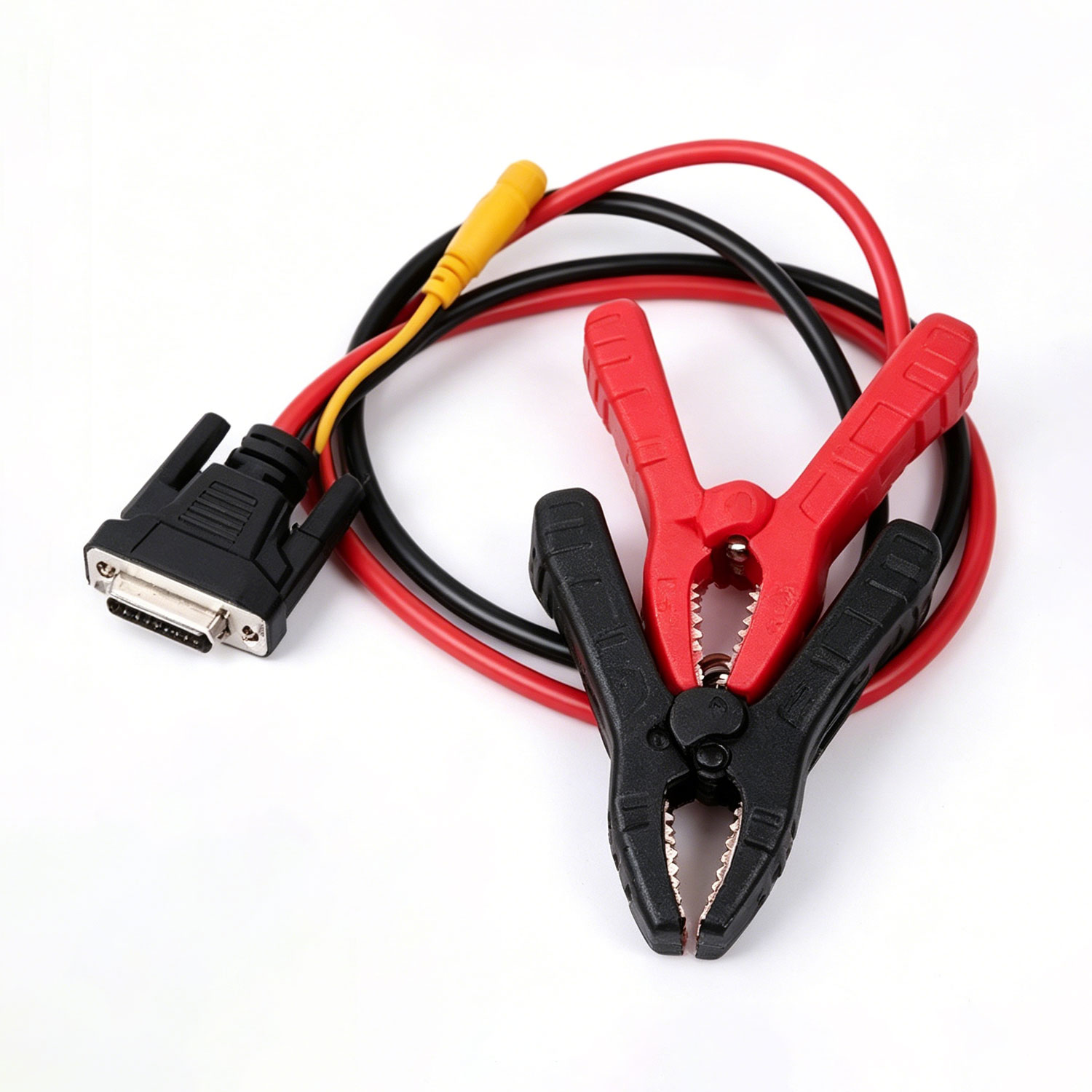
The current BT960 accessory page is deliberately narrow: it sells a power cable only and says the BT960 main tester is not included. Because an accessory page may cover a service part rather than every historical hardware revision, confirm the exact tester and cable before ordering or connecting.
- Record the BT960 model, serial or hardware revision, original order and any cable label.
- Photograph both connector faces, polarity markings, clamp arrangement and strain relief on the cable being replaced.
- Compare those details with the current accessory confirmation; do not rely on the tester family name alone.
- Power the tester down and disconnect it from every battery before removing the old cable by its housing.
- Inspect the tester socket for heat, corrosion or pushed-back contacts before seating the confirmed replacement without force.
- Run the tester’s normal power-on and known-battery check before returning it to service; stop if polarity, voltage or displayed status is abnormal.
How to replace battery-tester thermal printer paper
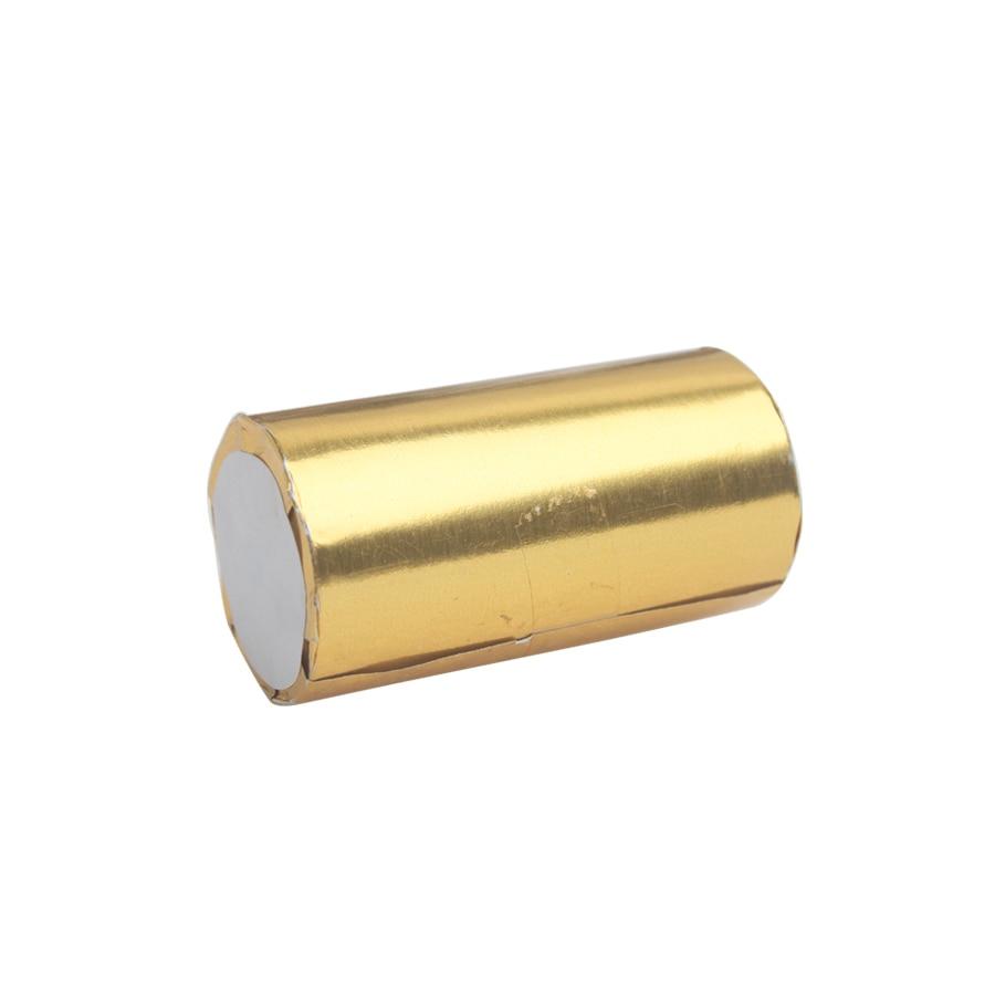
The current paper listing specifies five rolls of 57 × 30 mm thermal paper with a 0.5-inch (1/2-inch) core and names AUTOOL BT760, BT880 and BT960 printer-equipped testers. Printer compartments can vary by version or region, so compare the removed roll and the tester documentation before loading a refill.
- Finish the current print job, power the tester off if its instructions require it and open the printer cover without prying the hinge.
- Remove the old core and loose paper dust. Do not use liquid cleaner on the print head unless the tester procedure specifies it.
- Confirm the replacement roll is 57 × 30 mm with the 0.5-inch core and that the roll turns freely in the compartment.
- Load the thermal side toward the print head in the direction shown by the tester. If orientation is not marked, use the tester manual rather than repeatedly heating blank paper.
- Leave a straight paper tail through the exit, close the lid evenly and make sure the roll is not pinched.
- Power the tester on and print one short test. A blank or faint print calls for an orientation, paper, cover-pressure or print-head check—not a second roll forced into the compartment.
Frequently asked questions
Can I use a jump starter as the BT30 backup source?
The current BT30 product guidance says to use a fully charged 12 V vehicle battery and not a jump starter or power-bank charger. Use the source specified by the current device instructions and verify its voltage and polarity before connection.
Does BT30 guarantee that every memory and setting will be retained?
No. Retention depends on the vehicle supporting the OBD backup path and on uninterrupted voltage within the device and vehicle limits. A loose clamp, opened fuse, waking load or unsupported vehicle design can interrupt supply, so record settings and know the relearn plan first.
Can I turn the ignition on while BT30 is connected?
Keep the vehicle power switch and electrical appliances off during the battery-replacement workflow unless exact vehicle and current BT30 instructions explicitly require another state. BT30 is a limited support path, not a power source for normal vehicle loads.
What fuse should replace the installed BT30 fuse?
The retained BT30 manual identifies a built-in 3 A fuse. Follow the current device label and supplied manual for the exact unit; never bypass the fuse or install a larger value simply because the original opened.
Does the BT960 accessory listing include a tester?
No. The current page describes a power-cable accessory only. Confirm the exact BT960 version and required part before ordering.
Which paper fits the listed AUTOOL battery testers?
The current refill listing specifies 57 × 30 mm thermal paper with a 0.5-inch core for named BT760, BT880 and BT960 printer-equipped testers. Confirm the actual printer compartment and removed roll because model versions may differ.
Final battery-accessory checklist
- Exact vehicle battery procedure permits OBD backup support
- BT30, 3 A fuse, clamps, OBD terminals, cable and display pass inspection
- Fully charged 12 V vehicle battery is stable and correctly polarized
- Ignition and accessories remain off and the vehicle is in the required low-load state
- Displayed voltage/current remain plausible with no alarm, heating or fuse opening
- New battery is correct, secured and connected before BT30 removal
- BT960 replacement cable matches the exact tester version, connector and polarity
- Printer paper matches 57 × 30 mm, 0.5-inch core and actual device compartment
- Vehicle settings, tester power-up and printer test are checked after service
The best battery-service accessory workflow keeps every role separate: BT30 provides a carefully limited backup path, a replacement tester cable restores one identified connection, and thermal paper restores one verified printer supply. Match first, control power second, and do not let a small accessory become an uncontrolled electrical variable.




Comments 0
Questions, fixes, and real-world diagnostic notes from readers.
Be the first to share a diagnostic result or ask a follow-up question.